Paste this into Claude Code (VS Code panel, Adom editor, or terminal) to install:
Search the Adom Wiki for the molecule "USB2532 HUB-C" (slug: usb2532-hub-c) at https://wiki-ufypy5dpx93o.adom.cloud/wiki/molecules/usb2532-hub-c. Download its symbol (.kicad_sym), footprint (.kicad_mod), and 3D model (.glb/.step) assets into my current KiCad project under symbols/, footprints/, and 3dmodels/ directories. Register them in the project library tables. Show me the files once installed.
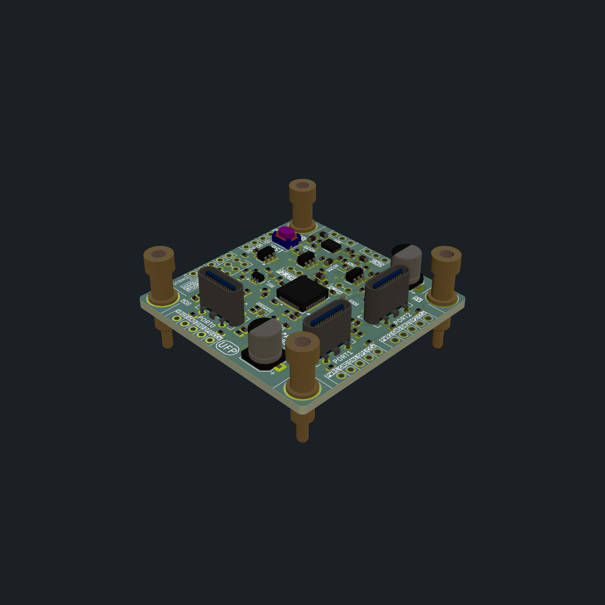
USB 2.0 hub molecule based on the Microchip USB2532I — 38×38 mm, 1 upstream + 2 downstream USB-C ports, self-powered with on-board 3.3V LDO, I2C EEPROM for configuration, and 30 machine contacts + 4 machine pins. Designed for Adom workcell USB distribution.
How It Works
The three USB-C 2.0 connectors are the primary user-facing interface for this molecule. J1 (upstream) connects to the USB host; J2 and J3 (downstream) connect to USB devices. The downstream ports provide power delivery to connected devices via per-port power switches (AP22615) with overcurrent protection.
All input power comes through the machine contacts only — the hub does not draw power from the upstream USB host. The workcell +5V rail feeds in through MP1/MP2 and MC20–MC22, powering the hub IC, the 3.3V LDO, and the downstream port power switches. This self-powered topology means downstream devices get full 5V power from the workcell supply regardless of what the USB host can source.
Overview
| Property | Value |
|---|
| Molecule ID | usb2532-hub-c |
| Board Size | 38.0 × 38.0 mm |
| Hub IC | USB2532I-1080AEN (Microchip, QFN-36) — USB 2.0, 2-port hub |
| EEPROM | 24LC04BT-I/OT — 4 Kbit I2C, stores hub configuration |
| Regulator | MCP1725T-ADJE/MC — adjustable LDO, set for 3.3V |
| Power Switches | 2× AP22615AWU — per-port power control with overcurrent protection |
| ESD Protection | 3× TPD2EUSB30DRTR — one per USB-C port |
| USB Ports | J1 (upstream UFP), J2 (downstream port 1), J3 (downstream port 2) |
| Crystal | 24 MHz |
| Machine Contacts | 30 contacts + 4 corner machine pins |
| KiCad Version | 7/8 |
| Design Reference | SMSC EVB-USB2534BC-01 evaluation board |
Key ICs
| Ref | Part | Package | Function |
|---|
| U4 | USB2532I-1080AEN | QFN-36 | USB 2.0 hub controller, 2 downstream ports |
| U7 | 24LC04BT-I/OT | SOT-23-5 | 4 Kbit I2C EEPROM for hub configuration |
| U5 | MCP1725T-ADJE/MC | DFN-8 | Adjustable LDO regulator (3.3V output) |
| U1 | AP22615AWU | SOT-23-5 | Port 1 power switch with OCS |
| U3 | AP22615AWU | SOT-23-5 | Port 2 power switch with OCS |
| U6 | TPD2EUSB30DRTR | DRT-3 | Upstream USB ESD protection |
| U8 | TPD2EUSB30DRTR | DRT-3 | Downstream port 1 ESD protection |
| U9 | TPD2EUSB30DRTR | DRT-3 | Downstream port 2 ESD protection |
Machine Contact Pin Mapping
4 corner machine pins + 30 machine contacts on all 4 edges.
Corner Machine Pins
| Pin | Position | Net | Function |
|---|
| MP1 | Top-left (16, 24) | +5V | 5V power input |
| MP2 | Top-right (48, 24) | +5V | 5V power input |
| MP3 | Bottom-left (16, 56) | GND | Ground |
| MP4 | Bottom-right (48, 56) | GND | Ground |
Left Edge — Control & Config
| Contact | Net | Function |
|---|
| MC19 | GND | Ground |
| MC17 | /RX | UART RX (hub debug) |
| MC18 | /TX | UART TX (hub debug) |
| MC16 | +3V3 | 3.3V output |
| MC1 | /SCL/CFG_SEL0 | I2C clock / config strap 0 |
| MC2 | /SDA/SMBDATA | I2C data / SMBus data |
| MC3 | /RESET | Hub reset |
| MC5 | GND | Ground |
| MC4 | /VBUS_DET | Upstream VBUS detect |
Top Edge — Power
| Contact | Net | Function |
|---|
| MC20 | +5V | 5V power |
| MC21 | +5V | 5V power |
| MC22 | +5V | 5V power |
| MC23 | GND | Ground |
| MC24 | GND | Ground |
| MC25 | GND | Ground |
Right Edge — USB Data & Downstream
| Contact | Net | Function |
|---|
| MC27 | /CC2_2 | Port 2 CC2 |
| MC28 | /USB2_DP | Port 2 USB D+ |
| MC29 | /USB2_DN | Port 2 USB D- |
| MC30 | GND | Ground |
| MC26 | /PWR2 | Port 2 power enable |
| MC7 | /CC2_1 | Port 1 CC2 |
| MC8 | /USB1_DP | Port 1 USB D+ |
| MC9 | /USB1_DN | Port 1 USB D- |
| MC10 | GND | Ground |
| MC6 | /PWR1 | Port 1 power enable |
Bottom Edge — Upstream USB
| Contact | Net | Function |
|---|
| MC11 | /VBUS_UP | Upstream VBUS |
| MC12 | /CC2_0 | Upstream CC2 |
| MC13 | /USB_UP_DP | Upstream USB D+ |
| MC14 | /USB_UP_DN | Upstream USB D- |
| MC15 | GND | Ground |
Configuration Modes
The hub supports two configuration modes selected via solder jumpers:
| Mode | CFG_SEL1 (JP5) | CFG_SEL0 (JP4) | Use |
|---|
| Straps & OTP, Self Pwr | 0 (open) | 0 (open) | Initial bring-up, blank EEPROM |
| I2C EEPROM & OTP | 1 (bridged) | 1 (bridged) | After EEPROM is programmed |
JP3 bridges SDA to +3V3 (I2C pull-up).
Power Architecture
+5V input (MC20-22 or MP1/MP2)
  │
  ├─→ FB1 (ferrite bead) → VBUS upstream (J1)
  ├─→ U1 (AP22615) → Port 1 power (J2)
  ├─→ U3 (AP22615) → Port 2 power (J3)
  └─→ U5 (MCP1725) → +3V3 (hub logic, EEPROM)
Self-powered topology — the hub provides power to downstream ports from the workcell +5V rail, not from the upstream USB host.
Status LEDs
| LED | Color | Function |
|---|
| D1 | Green | 3.3V power good |
| D2 | Red | Reset indicator |
| D3 | Yellow | Hub activity |
| D4 | Green | Port 1 power good |
| D5 | Red | Overcurrent fault |
| D6 | Green | Port 2 power good |
Solder Jumpers
| Jumper | Default | Function |
|---|
| JP1 | Bridged | Port 1 power enable routing |
| JP2 | Bridged | Port 2 power enable routing |
| JP3 | Bridged | SDA I2C pull-up |
| JP4 | Bridged | CFG_SEL0 (config mode select) |
| JP5 | Bridged | CFG_SEL1 (config mode select) |
EEPROM & Firmware
The project includes firmware tools for EEPROM programming:
firmware/eeprom.bin — pre-built EEPROM binaryfirmware/usb2532_eeprom.py — Python programming scripttest/EEPROM_PROGRAMMING_GUIDE.md — programming instructionstest/USB2532_Config_v1.2.json — hub configurationtest/USB2532_HUB-C_Test_Procedure.md — full functional test procedure
Debug & Test Points
| Test Point | Signal | Function |
|---|
| TP1 | — | General probe point |
| TP2 | — | General probe point |
| TP3 | — | General probe point |
| SW1 | RESET | Manual hub reset button |
Fabrication
KiCad project files included. STEP model available for mechanical integration.
3D Models
USB2532_HUB-C.glb — assembled board GLBUSB2532_HUB-C.step — STEP model for mechanical CAD
No sub-skills yet. Be the first to contribute one!