💬Sample promptsPaste any of these into Claude Code to use this molecule
RP2040 CANFind the RP2040 CAN bus molecule
PICAN pinoutShow the pin mapping for the RP2040 PICAN molecule
CAN moleculeI need a CAN FD molecule for my workcell
RP2040 castellatedWhat RP2040 castellated molecules do we have?
⚡Install this molecule
Paste this into Claude Code (VS Code panel, Adom editor, or terminal) to install:
Search the Adom Wiki for the molecule "RP2040 PICAN Castellated Molecule v1" (slug: rp2040-pican-castellated-v1) at https://wiki-ufypy5dpx93o.adom.cloud/wiki/molecules/rp2040-pican-castellated-v1. Download its symbol (.kicad_sym), footprint (.kicad_mod), and 3D model (.glb/.step) assets into my current KiCad project under symbols/, footprints/, and 3dmodels/ directories. Register them in the project library tables. Show me the files once installed.
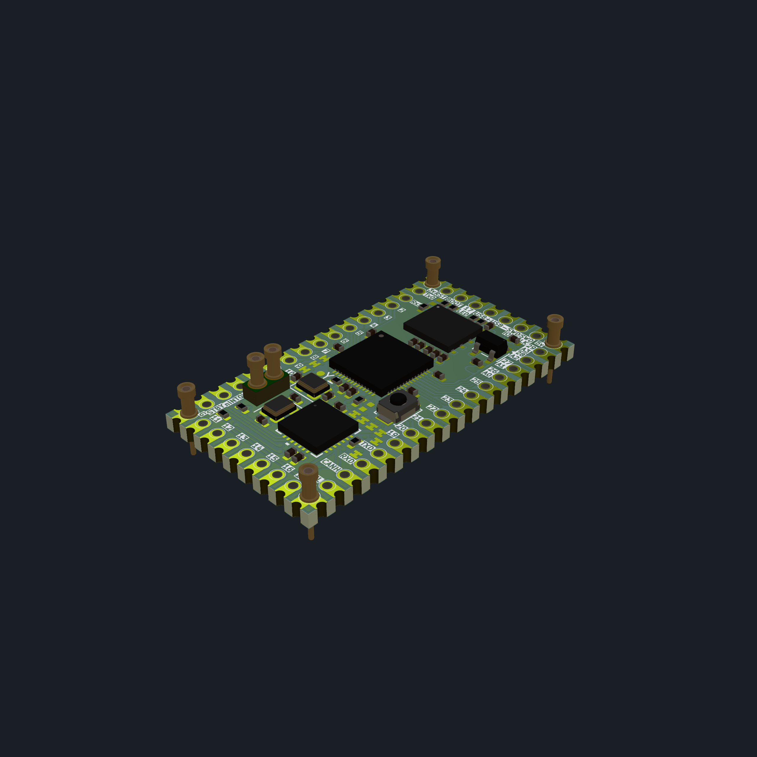
Castellated RP2040 molecule with integrated MCP251863 CAN bus controller/transceiver — 19×35 mm, 4 corner machine pins, 49 castellated machine contacts. USB-C, 16 MB QSPI flash, SWD debug, and 120 Ω CAN termination on-board.
Overview
Property
Value
Molecule ID
rp2040-pican-castellated-v1
Board Size
19.0 × 35.0 mm
Layers
2
MCU
RP2040 (Raspberry Pi, QFN-56)
CAN Controller
MCP251863T-E/9PX (Microchip, integrated CAN FD controller + transceiver)
Flash
W25Q128JVPIQ — 16 MB QSPI
Regulator
AP2112K-3.3 (3.3V LDO from 5V input)
USB
USB-C 2.0 with USBLC6-2P6 ESD protection
Crystal
12 MHz (RP2040), 40 MHz (MCP251863)
Castellated Pads
49 machine contacts + 4 corner machine pins
KiCad Version
7/8
Key ICs
Ref
Part
Package
Function
U4
RP2040
QFN-56
Dual-core Arm Cortex-M0+ MCU
U2
MCP251863T-E/9PX
VQFN-28
CAN FD controller + transceiver (SPI interface)
U3
W25Q128JVPIQ
WSON-8
16 MB QSPI flash
U6
AP2112K-3.3
SOT-23-5
3.3V 600mA LDO regulator
U1
USBLC6-2P6
SOT-23-6
USB ESD protection
U5
74LVC1T45
SOT-23-5
Level translator (LED data)
Machine Contact Pin Mapping
4 corner machine pins (X1–X4) for power/ground, 49 castellated contacts for signals.
Corner Machine Pins
Pin
Position
Net
Function
X1
Bottom-left (1, 7)
GND
Ground
X2
Top-left (1, -25)
+3V3
3.3V output
X3
Top-right (17, -25)
+5V
5V input
X4
Bottom-right (17, 7)
GND
Ground
Left Edge Contacts (bottom to top)
Contact
Net
Function
X54
STBY
CAN standby control
X43
nINT0/GPIO0/XSTBY
CAN interrupt 0 / GPIO0
X42
nINT1/GPIO1
CAN interrupt 1 / GPIO1
X47
nINT
CAN interrupt
X15
GPIO10
General purpose I/O
X14
GPIO9
General purpose I/O
X13
GPIO8
General purpose I/O
X12
GPIO7
General purpose I/O
X11
GPIO6
General purpose I/O
X10
GPIO5
General purpose I/O
X9
GPIO4
General purpose I/O
X8
GPIO3 / SCL1
I2C1 clock
X7
GPIO2 / SDA1
I2C1 data
X6
GPIO1 / RX0
UART0 RX
X5
GPIO0 / TX0
UART0 TX
Right Edge Contacts (bottom to top)
Contact
Net
Function
X56
CANL
CAN Low bus line
X55
CANH
CAN High bus line
X44
RXD
CAN RX data
X53
TXD
CAN TX data
X23
GPIO19
General purpose I/O
X24
GPIO20 / SDI
SPI data in
X25
GPIO21 / CS
SPI chip select
X26
GPIO22 / SCK
SPI clock
X27
GPIO23 / SDO
SPI data out
X37
GPIO24
General purpose I/O
X29
GPIO25
General purpose I/O
X30
A0 (GPIO26)
ADC channel 0
X31
A1 (GPIO27)
ADC channel 1
X32
A2 (GPIO28)
ADC channel 2
X33
A3 (GPIO29)
ADC channel 3
Top Edge Contacts (left to right)
Contact
Net
Function
X57
RST
Reset
X36
BOOT
Bootloader select
X22
GPIO17 / LED
User LED data line
X41
USB+
USB data positive
X40
USB-
USB data negative
X35
SWD_IO
SWD debug data
X34
SWD_CLK
SWD debug clock
Bottom Edge Contacts (left to right)
Contact
Net
Function
X16
GPIO11
General purpose I/O
X17
GPIO12
General purpose I/O
X18
GPIO13
General purpose I/O
X19
GPIO14
General purpose I/O
X20
GPIO15
General purpose I/O
X21
GPIO16
General purpose I/O
X38
GPIO18
General purpose I/O
CAN Bus Interface
The MCP251863T provides integrated CAN FD controller and transceiver connected to the RP2040 via SPI. Features:
KiCad project source bundle — schematic, PCB, GLB 3D model, custom footprints, and JLCPCB production files
file
1.8 MB
Sub-Skills
?
What are Sub-Skills?
Sub-skills are community-contributed AI skill extensions for this component.
They teach AI assistants about specific tools, configurators, or workflows.
Examples:
A manufacturer’s configuration tool for a motor controller
A community-written design guide for an amplifier circuit
An automated test/validation script for a sensor module
How to add one: Click Add Sub-Skill, provide the URL
to your skill and a brief description. Submissions are reviewed by the Adom team
before going live.
No sub-skills yet. Be the first to contribute one!