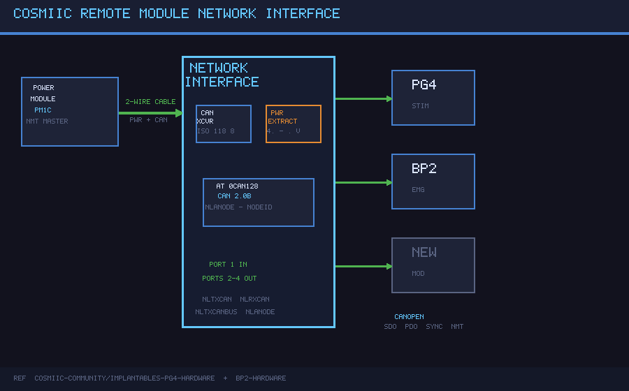
The Remote Module Network Interface is the shared circuit block present on every COSMIIC remote module (PG4, BP2, and derivatives). It bridges the AT90CAN128's built-in CAN controller to the implanted 2-conductor network, extracts regulated 5V from the network supply, and fans out to 4 ports (1 upstream in + 3 downstream out) for branching tree topology.
How it works
Every remote module connects to the COSMIIC implanted network through a single 2-conductor cable. That cable carries both the CANopen differential bus and the DC supply voltage on the same conductors (NET_P = CANH / supply+, NET_N = CANL / supply return). The network interface circuit:
- Extracts regulated 5V — NET_P (4.7–9.6 V from the PM) feeds the U2 LDO; regulated 5V powers the AT90CAN128 and the CAN transceiver
- Transceives CAN — U1 (TJA1050T) bridges the AT90CAN128's digital CANTX/CANRX pins to the physical CANH/CANL bus
- Fans out to 4 ports — J1–J4 connectors branch the same CAN bus to 1 upstream input + 3 downstream outputs
- Hardware node addressing — MC_ANODE exposes the hardware node address line to the AT90CAN128
U1's Rs pin is pulled low through R1 (10 kΩ) for slope-controlled mode, which limits dV/dt on the bus edges and reduces EMI — important for implantable devices.
Hardware
| Parameter | Value |
|---|---|
| CAN Controller | AT90CAN128 built-in (ISO 11898, CAN 2.0B) |
| CAN Transceiver | NXP TJA1050T (SOIC-8, 1 Mbps, 5V) |
| LDO Regulator | MIC5205-5.0YM5 (SOT-23-5, 5V, 150 mA) |
| Network Cable | 2-conductor (CAN differential + power superimposed) |
| Network Ports | 4 total — J1 upstream in, J2–J4 downstream out |
| Topology | Branching tree (up to 24 nodes from a single PM) |
| Network Voltage | 4.7–9.6 V (adjustable from PM) |
| Output Voltage | 5 V regulated |
| Protocol | CANopen |
| Node Addressing | Hardware-configured (MC_ANODE) |
| PCB Size | 32 × 24 mm Adom molecule |
Components
| Ref | Part | Value | Package | JLCPCB |
|---|---|---|---|---|
| U1 | NXP TJA1050T | CAN transceiver, 1 Mbps | SOIC-8 | C6952 |
| U2 | MIC5205-5.0YM5 | 5V LDO, 150 mA, 16V max in | SOT-23-5 | C89758 |
| J1–J4 | 2-pin header | COSMIIC network port | 2.54mm pitch | — |
| C1 | 100nF | TJA1050T VCC decoupling | 0402 | C1525 |
| C2 | 10µF | LDO input cap | 0805 | — |
| C3 | 22µF | LDO output cap (stability) | 0805 | — |
| C4 | 100nF | TJA1050T VREF bypass | 0402 | C1525 |
| R1 | 10 kΩ | TJA1050T slope control (Rs) | 0402 | C25744 |
Production note: For the full 4.7–9.6 V network range, replace U2 with LM1117S-5.0 (C126028, SOT-223-3, 800 mA) which handles up to 15 V input.
Signal Net Names
| Net | Description |
|---|---|
NLTXCAN / MC_CANTX | CAN TX from AT90CAN128 to U1.TXD |
NLRXCAN / MC_CANRX | CAN RX from U1.RXD to AT90CAN128 |
NLTXCANBUS / CANH | CAN bus positive on network cable |
NLTXCANBUS / CANL | CAN bus negative on network cable |
NLANODE / MC_ANODE | Hardware node address input |
Machine Contacts
| Contact | Side | Function |
|---|---|---|
| MC_CANTX | Left | CAN TX from AT90CAN128 → U1.TXD |
| MC_CANRX | Left | CAN RX from U1.RXD → AT90CAN128 |
| MC_VCC5V | Left | 5V regulated output to module |
| MC_GND | Left | Ground reference |
| MC_VIN | Right | Network supply input (4.7–9.6V) |
| MC_CANH | Right | CAN bus positive |
| MC_CANL | Right | CAN bus negative |
| MC_ANODE | Right | CANopen node address |
Architecture
        Network Cable (2-wire: NET_P/CANH and NET_N/CANL)
                │
    ┌───────────▼─────────────┐
    │   J1 — Port 1 (in)      │
    └───────────┬─────────────┘
                │
    ┌───────────▼──────────────────────────────────┐
    │        Network Interface (32×24mm)           │
    │                                              │
    │  ┌──────────────┐   ┌────────────────────┐  │
    │  │ U2 MIC5205   │   │ U1 TJA1050T        │  │
    │  │ 5V LDO       │   │ CAN Transceiver    │  │
    │  │ NET_P → 5V   │   │ CANTX/CANRX (MCU)  │  │
    │  └──────┬───────┘   │ CANH/CANL (bus)    │  │
    │         │ VCC       └──────┬──────────────┘  │
    │         └──────────────────┤                 │
    │                            │ CANH / CANL     │
    └────────────────────────────┼─────────────────┘
                │          │          │
    ┌───────────▼─┐ ┌───────▼──┐ ┌───▼────────┐
    │ J2 (out 1)  │ │J3 (out 2)│ │J4 (out 3)  │
    └─────────────┘ └──────────┘ └────────────┘
CANopen Protocol
The PM acts as NMT master; remote modules are NMT slaves.
| Message Type | Direction | Purpose |
|---|---|---|
| NMT | PM → Module | State machine transitions (Operational, Pre-op, Reset) |
| SYNC | PM → All | Cyclic timing reference (controls stimulation frequency, data windows) |
| SDO | Bidirectional | Point-to-point Object Dictionary read/write (configuration, testing) |
| PDO | Module → PM | High-speed broadcast of sensor data / stimulation status |
| Emergency | Module → PM | Fault reporting |
Build
EDA: tscircuit (TSX) — source bundle included in Files below.
LDO note: Production modules use LM1117S-5.0 (C126028, SOT-223) which handles the full 4.7–9.6V network range. The SOT-23-5 MIC5205 in this reference design targets bench testing where network voltage is kept ≤6V.
Firmware: COSMIIC-Community/Implantables-PG4-App / Implantables-BP2-App — C, AVR toolchain
Source
All design files are open source under CERN-OHL-P-2.0 (hardware) and MIT (firmware).
Files
| File | Description |
|---|---|
cosmiic-network-interface-source.tar.gz | tscircuit project source (lib/index.tsx, package.json, config) |
schematic.svg | Circuit schematic (all connections) |
pcb.svg | PCB layout (32×24mm, component placement) |
3d.glb | 3D board model |
Reference Implementation
The equivalent analog circuit appears as a dedicated schematic sheet in every remote module Altium project:
- PG4 — page 4 of 8 ("CAN Interface") in COSMIIC-Community/Implantables-PG4-Hardware
- BP2 — page 4 of 6 ("Network Interface") in COSMIIC-Community/Implantables-BP2-Hardware
NSF Relevance
The standardized remote module network interface enables multi-node implantable research systems with a single power and communication cable per branch. Researchers can add sensing or stimulation nodes to a running implant without architectural changes, enabling adaptive closed-loop protocols with real-time bidirectional data flow.
Science Drivers
implantable_healthcare
Created by: noah Version: v1 Category: other