CSD18540Q5B — 60 V N-channel Power MOSFET
Texas Instruments CSD18540Q5B: 60 V, N-channel NexFET power MOSFET in SON 5x6 mm. 1.8 mOhm RDS(on) at VGS=10 V, 41 nC total gate charge, 205 A continuous drain current.
Paste this into Claude Code (VS Code panel, Adom editor, or terminal) to install:
Search the Adom Wiki for the datasheet "CSD18540Q5B — 60 V N-channel Power MOSFET" (slug: csd18540q5b) at https://wiki-ufypy5dpx93o.adom.cloud/wiki/datasheets/csd18540q5b. Download the standardized markdown and extracted diagram images into my project's datasheets/csd18540q5b/ directory. Show me the key specifications and pin configuration.
60-V, N-Channel NexFET™ Power MOSFET — Texas Instruments
Ultra-low-Qg / low-RDS(on) N-channel MOSFET in a SON 5 mm × 6 mm package. Designed for synchronous rectification, isolated-converter primary switches, motor control, and DC-DC conversion.
Features
- • Ultra-low Qg and Qgd
- • Low thermal resistance (R<sub>θJC</sub> typ 0.8 °C/W)
- • Avalanche rated (E<sub>AS</sub> = 320 mJ)
- • Lead-free, RoHS, halogen-free
- • SON 5 mm × 6 mm plastic package

60-V, N-Channel NexFET™ Power MOSFET — Texas Instruments
Ultra-low-Qg / low-RDS(on) N-channel MOSFET in a SON 5 mm × 6 mm package. Designed for synchronous rectification, isolated-converter primary switches, motor control, and DC-DC conversion.
Summary
| Parameter | Typical | Unit |
|---|---|---|
| V<sub>DS</sub> (Drain-to-Source Voltage) | 60 | V |
| Q<sub>g</sub> (Gate Charge Total, V<sub>GS</sub> = 10 V) | 41 | nC |
| Q<sub>gd</sub> (Gate-to-Drain Charge) | 6.7 | nC |
| R<sub>DS(on)</sub> @ V<sub>GS</sub> = 10 V | 1.8 | mΩ |
| R<sub>DS(on)</sub> @ V<sub>GS</sub> = 4.5 V | 2.6 | mΩ |
| V<sub>GS(th)</sub> (Threshold Voltage) | 1.9 | V |
Package: SON 5.00 mm × 6.00 mm, 8-pin (VSON-CLIP / DNK), part mark CSD18540.
Absolute Maximum Ratings (T<sub>A</sub> = 25 °C)
| Symbol | Parameter | Value | Unit |
|---|---|---|---|
| V<sub>DS</sub> | Drain-to-Source Voltage | 60 | V |
| V<sub>GS</sub> | Gate-to-Source Voltage | ±20 | V |
| I<sub>D</sub> | Continuous Drain Current (package-limited) | 100 | A |
| I<sub>D</sub> | Continuous Drain Current (silicon-limited, T<sub>C</sub> = 25 °C) | 205 | A |
| I<sub>D</sub> | Continuous Drain Current (T<sub>A</sub> = 25 °C) | 29 | A |
| I<sub>DM</sub> | Pulsed Drain Current (T<sub>A</sub> = 25 °C) | 400 | A |
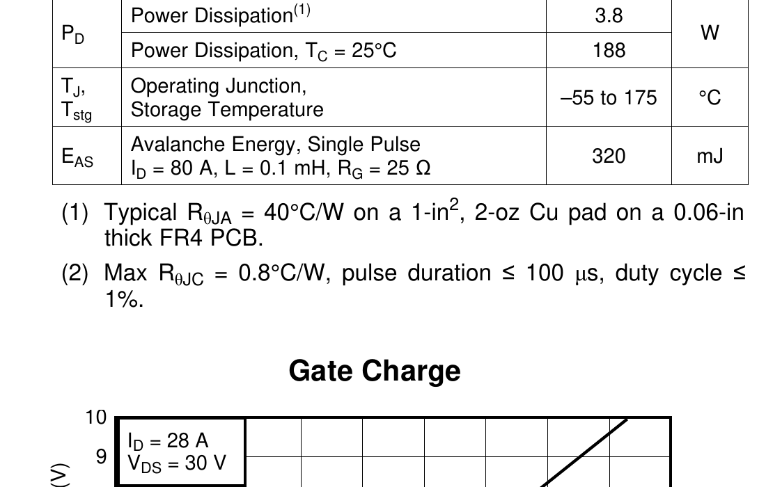
| P<sub>D</sub> | Power Dissipation (T<sub>A</sub> = 25 °C) | 3.8 | W |
| P<sub>D</sub> | Power Dissipation (T<sub>C</sub> = 25 °C) | 188 | W |
| T<sub>J</sub>, T<sub>stg</sub> | Operating Junction, Storage Temperature | −55 to 175 | °C |
| E<sub>AS</sub> | Avalanche Energy, single pulse (I<sub>D</sub> = 80 A, L = 0.1 mH, R<sub>G</sub> = 25 Ω) | 320 | mJ |
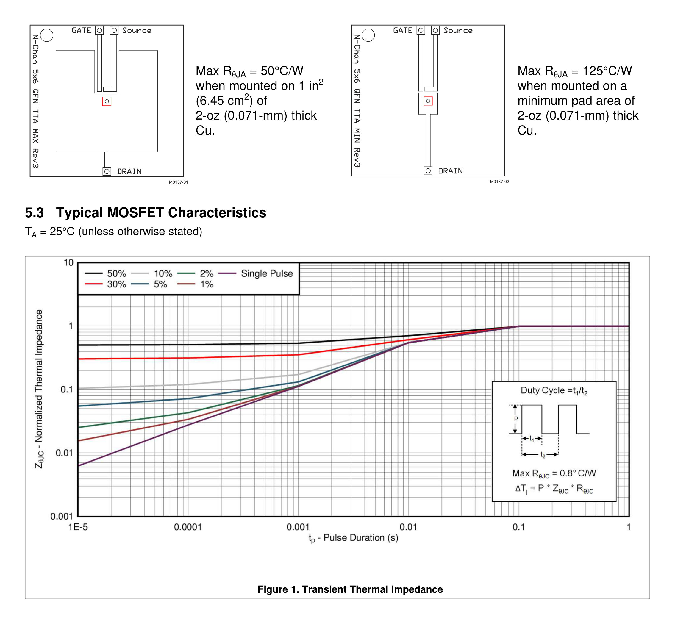
Notes: Typical R<sub>θJA</sub> = 40 °C/W on a 1-in², 2-oz Cu pad, 0.06-in FR4. Max R<sub>θJC</sub> = 0.8 °C/W, pulse ≤ 100 µs, duty ≤ 1 %.
Electrical Characteristics (T<sub>A</sub> = 25 °C unless noted)
Static
| Symbol | Parameter | Test Conditions | Min | Typ | Max | Unit |
|---|---|---|---|---|---|---|
| BV<sub>DSS</sub> | Drain-to-source voltage | V<sub>GS</sub> = 0 V, I<sub>D</sub> = 250 µA | 60 | V | ||
| I<sub>DSS</sub> | Drain-to-source leakage | V<sub>GS</sub> = 0 V, V<sub>DS</sub> = 48 V | 1 | µA | ||
| I<sub>GSS</sub> | Gate-to-source leakage | V<sub>DS</sub> = 0 V, V<sub>GS</sub> = ±20 V | 100 | nA | ||
| V<sub>GS(th)</sub> | Gate threshold voltage | V<sub>DS</sub> = V<sub>GS</sub>, I<sub>D</sub> = 250 µA | 1.5 | 1.9 | 2.3 | V |
| R<sub>DS(on)</sub> | On resistance | V<sub>GS</sub> = 4.5 V, I<sub>D</sub> = 28 A | 2.6 | 3.3 | mΩ | |
| R<sub>DS(on)</sub> | On resistance | V<sub>GS</sub> = 10 V, I<sub>D</sub> = 28 A | 1.8 | 2.2 | mΩ | |
| g<sub>fs</sub> | Transconductance | V<sub>DS</sub> = 6 V, I<sub>D</sub> = 28 A | 116 | S |
Dynamic (V<sub>GS</sub> = 0 V, V<sub>DS</sub> = 30 V, f = 1 MHz unless noted)
| Symbol | Parameter | Typ | Max | Unit |
|---|---|---|---|---|
| C<sub>iss</sub> | Input capacitance | 3250 | 4230 | pF |
| C<sub>oss</sub> | Output capacitance | 622 | 808 | pF |
| C<sub>rss</sub> | Reverse transfer capacitance | 15 | 20 | pF |
| R<sub>G</sub> | Series gate resistance | 0.8 | 1.6 | Ω |
| Q<sub>g</sub> (4.5 V) | Gate charge total | 20 | 26 | nC |
| Q<sub>g</sub> (10 V) | Gate charge total | 41 | 53 | nC |
| Q<sub>gd</sub> | Gate-to-drain charge | 6.7 | nC | |
| Q<sub>gs</sub> | Gate-to-source charge | 8.8 | nC | |
| Q<sub>g(th)</sub> | Gate charge at threshold | 6.3 | nC | |
| Q<sub>oss</sub> | Output charge (V<sub>GS</sub> = 0, V<sub>DS</sub> = 30 V) | 83 | nC | |
| t<sub>d(on)</sub> | Turn-on delay (V<sub>GS</sub> = 10 V, I<sub>DS</sub> = 28 A, R<sub>G</sub> = 0 Ω) | 6 | ns | |
| t<sub>r</sub> | Rise time | 13 | ns | |
| t<sub>d(off)</sub> | Turn-off delay | 20 | ns | |
| t<sub>f</sub> | Fall time | 3 | ns |
Diode Characteristics
| Symbol | Parameter | Test Conditions | Typ | Max | Unit |
|---|---|---|---|---|---|
| V<sub>SD</sub> | Diode forward voltage | I<sub>SD</sub> = 28 A, V<sub>GS</sub> = 0 V | 0.8 | 1 | V |
| Q<sub>rr</sub> | Reverse recovery charge | V<sub>DS</sub> = 30 V, I<sub>F</sub> = 28 A, di/dt = 300 A/µs | 145 | nC | |
| t<sub>rr</sub> | Reverse recovery time | 62 | ns |
Thermal
| Metric | Typ | Max | Unit |
|---|---|---|---|
| R<sub>θJC</sub> (Junction-to-case) | 0.8 | °C/W | |
| R<sub>θJA</sub> (Junction-to-ambient) | 50 | °C/W |
R<sub>θJC</sub> based on 1-in² (6.45 cm²), 2-oz (0.071 mm) Cu pad on 1.5-in × 1.5-in × 3.81-cm (1.52-mm) FR4 PCB.
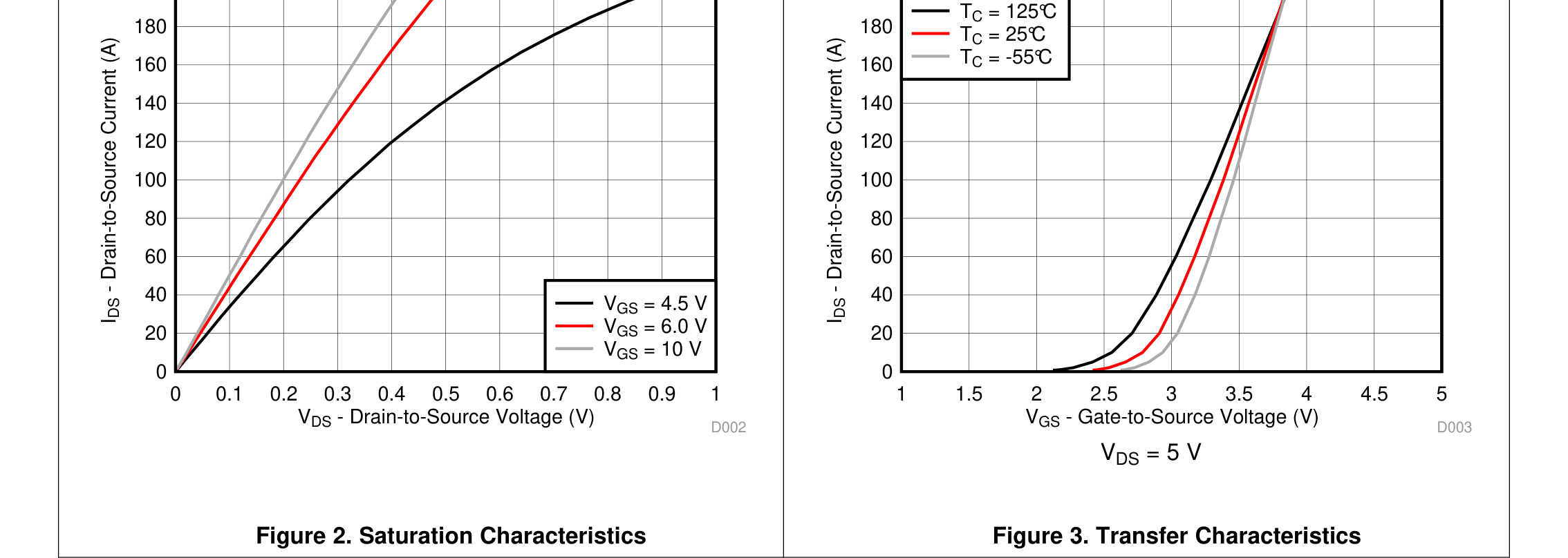
Typical Characteristics


Package and Ordering
- Package: SON 5.00 mm × 6.00 mm plastic (DNK / VSON-CLIP), 8 pins, body thickness 1.0 mm
- Orderable:
CSD18540Q5B— 2500 units on 13-inch reel,CSD18540Q5BT— 250 units on 7-inch reel - Lead finish: NIPDAU / SN, MSL Level 1 260 °C
- Operating temp: −55 to 175 °C
- Part marking:
CSD18540
Source
Datasheet: SLPS488B, Rev. B, April 2017
Applications
- DC-DC conversion
- Secondary-side synchronous rectifier
- Isolated-converter primary-side switch
- Motor control
Diagrams & Graphs (8)

# CSD18540Q5B
**60-V, N-Channel NexFET™ Power MOSFET** — Texas Instruments
Ultra-low-Qg / low-RDS(on) N-channel MOSFET in a SON 5 mm × 6 mm package. Designed for synchronous rectification, isolated-converter primary switches, motor control, and DC-DC conversion.
## Summary
| Parameter | Typical | Unit |
|---|---|---|
| V<sub>DS</sub> (Drain-to-Source Voltage) | 60 | V |
| Q<sub>g</sub> (Gate Charge Total, V<sub>GS</sub> = 10 V) | 41 | nC |
| Q<sub>gd</sub> (Gate-to-Drain Charge) | 6.7 | nC |
| R<sub>DS(on)</sub> @ V<sub>GS</sub> = 10 V | 1.8 | mΩ |
| R<sub>DS(on)</sub> @ V<sub>GS</sub> = 4.5 V | 2.6 | mΩ |
| V<sub>GS(th)</sub> (Threshold Voltage) | 1.9 | V |
Package: SON 5.00 mm × 6.00 mm, 8-pin (VSON-CLIP / DNK), part mark `CSD18540`.
## Features
- Ultra-low Qg and Qgd
- Low thermal resistance (R<sub>θJC</sub> typ 0.8 °C/W)
- Avalanche rated (E<sub>AS</sub> = 320 mJ)
- Lead-free, RoHS, halogen-free
- SON 5 mm × 6 mm plastic package
## Applications
- DC-DC conversion
- Secondary-side synchronous rectifier
- Isolated-converter primary-side switch
- Motor control
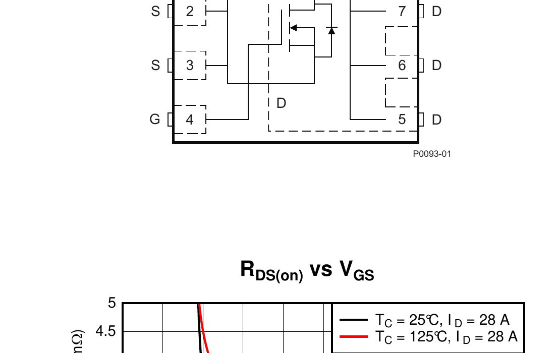
## Pin Configuration

Top view, SON 8-pin (DNK):
| Pin(s) | Name | Function |
|---|---|---|
| 1 | G | Gate |
| 2, 3, 4 | S | Source |
| 5, 6, 7, 8 | D | Drain |
## Absolute Maximum Ratings (T<sub>A</sub> = 25 °C)
| Symbol | Parameter | Value | Unit |
|---|---|---|---|
| V<sub>DS</sub> | Drain-to-Source Voltage | 60 | V |
| V<sub>GS</sub> | Gate-to-Source Voltage | ±20 | V |
| I<sub>D</sub> | Continuous Drain Current (package-limited) | 100 | A |
| I<sub>D</sub> | Continuous Drain Current (silicon-limited, T<sub>C</sub> = 25 °C) | 205 | A |
| I<sub>D</sub> | Continuous Drain Current (T<sub>A</sub> = 25 °C) | 29 | A |
| I<sub>DM</sub> | Pulsed Drain Current (T<sub>A</sub> = 25 °C) | 400 | A |
| P<sub>D</sub> | Power Dissipation (T<sub>A</sub> = 25 °C) | 3.8 | W |
| P<sub>D</sub> | Power Dissipation (T<sub>C</sub> = 25 °C) | 188 | W |
| T<sub>J</sub>, T<sub>stg</sub> | Operating Junction, Storage Temperature | −55 to 175 | °C |
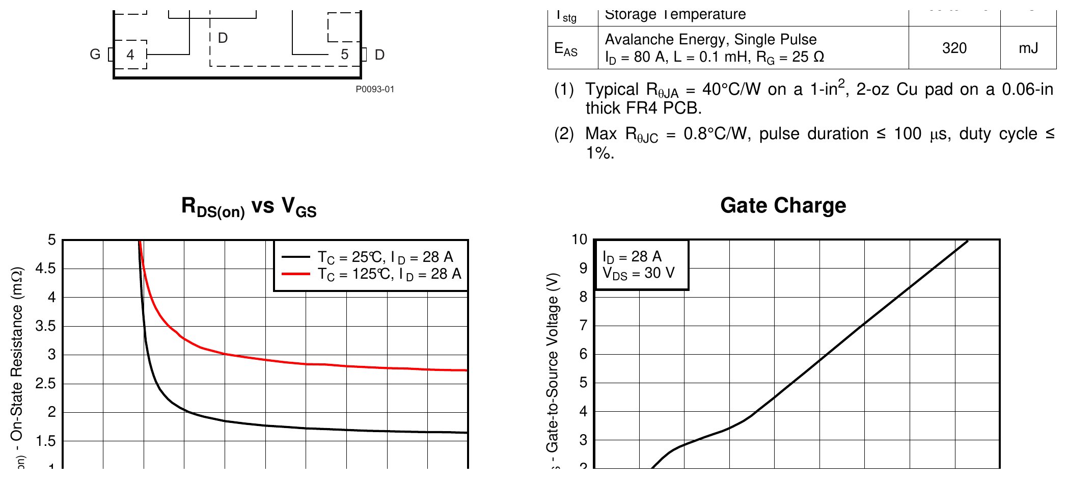
| E<sub>AS</sub> | Avalanche Energy, single pulse (I<sub>D</sub> = 80 A, L = 0.1 mH, R<sub>G</sub> = 25 Ω) | 320 | mJ |
Notes: Typical R<sub>θJA</sub> = 40 °C/W on a 1-in², 2-oz Cu pad, 0.06-in FR4. Max R<sub>θJC</sub> = 0.8 °C/W, pulse ≤ 100 µs, duty ≤ 1 %.
## Electrical Characteristics (T<sub>A</sub> = 25 °C unless noted)
### Static
| Symbol | Parameter | Test Conditions | Min | Typ | Max | Unit |
|---|---|---|---|---|---|---|
| BV<sub>DSS</sub> | Drain-to-source voltage | V<sub>GS</sub> = 0 V, I<sub>D</sub> = 250 µA | 60 | | | V |
| I<sub>DSS</sub> | Drain-to-source leakage | V<sub>GS</sub> = 0 V, V<sub>DS</sub> = 48 V | | | 1 | µA |
| I<sub>GSS</sub> | Gate-to-source leakage | V<sub>DS</sub> = 0 V, V<sub>GS</sub> = ±20 V | | | 100 | nA |
| V<sub>GS(th)</sub> | Gate threshold voltage | V<sub>DS</sub> = V<sub>GS</sub>, I<sub>D</sub> = 250 µA | 1.5 | 1.9 | 2.3 | V |
| R<sub>DS(on)</sub> | On resistance | V<sub>GS</sub> = 4.5 V, I<sub>D</sub> = 28 A | | 2.6 | 3.3 | mΩ |
| R<sub>DS(on)</sub> | On resistance | V<sub>GS</sub> = 10 V, I<sub>D</sub> = 28 A | | 1.8 | 2.2 | mΩ |
| g<sub>fs</sub> | Transconductance | V<sub>DS</sub> = 6 V, I<sub>D</sub> = 28 A | | 116 | | S |
### Dynamic (V<sub>GS</sub> = 0 V, V<sub>DS</sub> = 30 V, f = 1 MHz unless noted)
| Symbol | Parameter | Typ | Max | Unit |
|---|---|---|---|---|
| C<sub>iss</sub> | Input capacitance | 3250 | 4230 | pF |
| C<sub>oss</sub> | Output capacitance | 622 | 808 | pF |
| C<sub>rss</sub> | Reverse transfer capacitance | 15 | 20 | pF |
| R<sub>G</sub> | Series gate resistance | 0.8 | 1.6 | Ω |
| Q<sub>g</sub> (4.5 V) | Gate charge total | 20 | 26 | nC |
| Q<sub>g</sub> (10 V) | Gate charge total | 41 | 53 | nC |
| Q<sub>gd</sub> | Gate-to-drain charge | 6.7 | | nC |
| Q<sub>gs</sub> | Gate-to-source charge | 8.8 | | nC |
| Q<sub>g(th)</sub> | Gate charge at threshold | 6.3 | | nC |
| Q<sub>oss</sub> | Output charge (V<sub>GS</sub> = 0, V<sub>DS</sub> = 30 V) | 83 | | nC |
| t<sub>d(on)</sub> | Turn-on delay (V<sub>GS</sub> = 10 V, I<sub>DS</sub> = 28 A, R<sub>G</sub> = 0 Ω) | 6 | | ns |
| t<sub>r</sub> | Rise time | 13 | | ns |
| t<sub>d(off)</sub> | Turn-off delay | 20 | | ns |
| t<sub>f</sub> | Fall time | 3 | | ns |
### Diode Characteristics
| Symbol | Parameter | Test Conditions | Typ | Max | Unit |
|---|---|---|---|---|---|
| V<sub>SD</sub> | Diode forward voltage | I<sub>SD</sub> = 28 A, V<sub>GS</sub> = 0 V | 0.8 | 1 | V |
| Q<sub>rr</sub> | Reverse recovery charge | V<sub>DS</sub> = 30 V, I<sub>F</sub> = 28 A, di/dt = 300 A/µs | 145 | | nC |
| t<sub>rr</sub> | Reverse recovery time | | 62 | | ns |
## Thermal
| Metric | Typ | Max | Unit |
|---|---|---|---|
| R<sub>θJC</sub> (Junction-to-case) | | 0.8 | °C/W |
| R<sub>θJA</sub> (Junction-to-ambient) | | 50 | °C/W |
R<sub>θJC</sub> based on 1-in² (6.45 cm²), 2-oz (0.071 mm) Cu pad on 1.5-in × 1.5-in × 3.81-cm (1.52-mm) FR4 PCB.
## Typical Characteristics


## Package and Ordering
- **Package**: SON 5.00 mm × 6.00 mm plastic (DNK / VSON-CLIP), 8 pins, body thickness 1.0 mm
- **Orderable**: `CSD18540Q5B` — 2500 units on 13-inch reel, `CSD18540Q5BT` — 250 units on 7-inch reel
- **Lead finish**: NIPDAU / SN, MSL Level 1 260 °C
- **Operating temp**: −55 to 175 °C
- **Part marking**: `CSD18540`
## Source
Datasheet: [SLPS488B, Rev. B, April 2017](https://www.ti.com/lit/ds/symlink/csd18540q5b.pdf)
Sub-Skills
What are Sub-Skills?
Sub-skills are community-contributed AI skill extensions for this component.
They teach AI assistants about specific tools, configurators, or workflows.
Examples:
- A manufacturer’s configuration tool for a motor controller
- A community-written design guide for an amplifier circuit
- An automated test/validation script for a sensor module
How to add one: Click Add Sub-Skill, provide the URL
to your skill and a brief description. Submissions are reviewed by the Adom team
before going live.
Sub-skills are community-contributed AI skill extensions for this component. They teach AI assistants about specific tools, configurators, or workflows.
Examples:
- A manufacturer’s configuration tool for a motor controller
- A community-written design guide for an amplifier circuit
- An automated test/validation script for a sensor module
How to add one: Click Add Sub-Skill, provide the URL to your skill and a brief description. Submissions are reviewed by the Adom team before going live.
No sub-skills yet. Be the first to contribute one!