BMI270
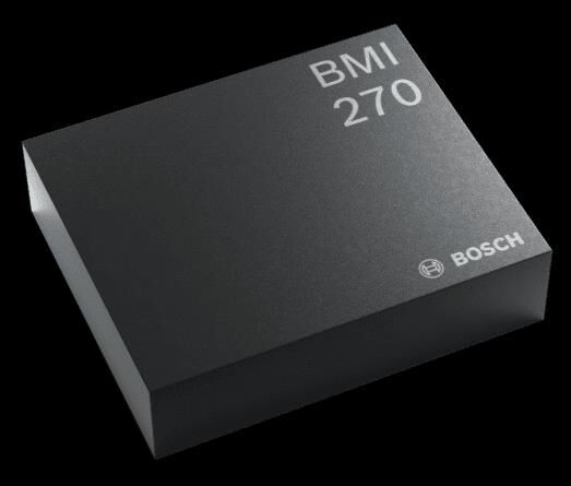
Bosch Sensortec BMI270. Ultra-low power 6-axis IMU (accel + gyro) for wearables. 16-bit, 685uA typ, I2C/SPI, wrist gestures, OIS support, LGA-14. Standardized datasheet with 15 extracted diagrams.
Paste this into Claude Code (VS Code panel, Adom editor, or terminal) to install:
Search the Adom Wiki for the datasheet "BMI270" (slug: bmi270) at https://wiki-ufypy5dpx93o.adom.cloud/wiki/datasheets/bmi270. Download the standardized markdown and extracted diagram images into my project's datasheets/bmi270/ directory. Show me the key specifications and pin configuration.
Source: Bosch Sensortec Datasheet (BST-BMI270-DS000-07) Manufacturer: Bosch Sensortec Part Number: BMI270 Document: BST-BMI270-DS000-07 — Rev 1.5, March 2023
Description
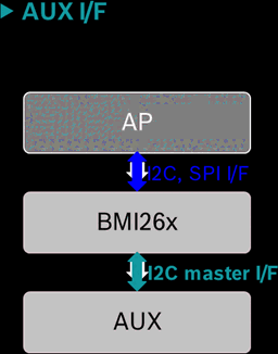
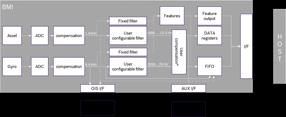
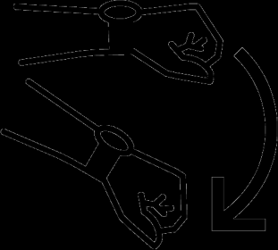
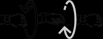
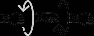
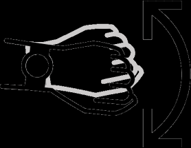
The BMI270 is a highly integrated, ultra-low power inertial measurement unit (IMU) optimized for wearable applications. It combines precise acceleration and angular rate (gyroscopic) measurement with intelligent on-chip motion-triggered interrupt features. The device integrates a 16-bit digital triaxial accelerometer and a 16-bit digital triaxial gyroscope in a compact 2.5 x 3.0 mm LGA package. The BMI270 includes dedicated wearable gesture recognition features such as wrist wear wakeup, step counting, activity recognition, wrist gestures (flick in/out, push arm down, pivot up, wrist jiggle), and significant motion detection. It supports I2C (Fast-mode Plus) and SPI (up to 10 MHz) primary interfaces, an auxiliary I2C master interface for connecting external sensors like magnetometers, and an OIS SPI slave interface for camera optical image stabilization with up to 6.4 kHz ODR and sub-millisecond group delay. A built-in 2 KB FIFO buffer, hardware-synchronized sensor timestamps, and a comprehensive power management unit enable efficient battery-powered system designs.
Key Specifications
Features
- • 16-bit triaxial accelerometer with +/-2g/+/-4g/+/-8g/+/-16g selectable range
- • 16-bit triaxial gyroscope with +/-125 to +/-2000 dps selectable range
- • Ultra-low power consumption: 685 uA typical in full ODR normal mode
- • Performance mode for gyroscope with noise as low as 0.007 dps/sqrt(Hz)
- • Rapid gyroscope startup: 2 ms in fast-start mode
- • Built-in power management unit (PMU) with advanced low-power modes
- • 2 KB on-chip FIFO buffer for accel, gyro, timestamps, and auxiliary sensor data
- • Hardware synchronization of accelerometer, gyroscope, and auxiliary sensor (< 1 us)
- • Sensortime stamps for accurate host/sensor time synchronization (< 40 us)
- • I2C Fast-mode Plus master interface hub for 1 auxiliary sensor (e.g., magnetometer)
- • 10 MHz SPI slave OIS interface for camera stabilization with up to 6.4 kHz ODR
- • Programmable low-pass filters: accel BW 5.5 to 740 Hz, gyro BW 11 to 751 Hz
- • Fast offset and sensitivity error compensation (CRT reduces gyro error to typ. 0.4%)
- • Wrist wear wakeup gesture detection
- • Step counter and step detector (wrist-worn optimized)
- • Activity and activity change recognition
- • Significant motion, any-motion, and no-motion detection
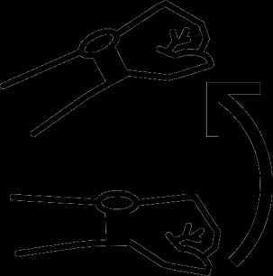
- • Wrist navigation gestures: flick in/out, push arm down, pivot up, wrist jiggle
- • 2 independent programmable interrupt output pins
- • RoHS compliant, halogen-free, lead-free
Pin Configuration
Source: Bosch Sensortec Datasheet (BST-BMI270-DS000-07) Manufacturer: Bosch Sensortec Part Number: BMI270 Document: BST-BMI270-DS000-07 — Rev 1.5, March 2023
Absolute Maximum Ratings
| Parameter | Condition | Min | Max | Unit |
|---|---|---|---|---|
| Supply Voltage (VDD) | VDD Pin | -0.3 | 4 | V |
| Supply Voltage (VDDIO) | VDDIO Pin | -0.3 | 4 | V |
| Voltage at Logic Pin | Non-Supply Pin | -0.3 | VDDIO+0.3, <4 | V |
| Storage Temperature | <= 65% rel. humidity | -50 | +150 | degC |
| NVM Data Retention | T=85 degC, after 15 cycles | 10 | — | years |
| Mechanical Shock | Duration <= 200 us | — | 20,000 | g |
| Mechanical Shock | Duration <= 1.0 ms | — | 2,000 | g |
| Free Fall | Onto hard surfaces | — | 1.8 | m |
| ESD (HBM) | Any pin | — | 2 | kV |
| ESD (CDM) | — | — | 500 | V |
| ESD (MM) | JESD22A115C | — | 200 | V |
Electrical Characteristics
Accelerometer
| Parameter | Condition | Min | Typ | Max | Unit |
|---|---|---|---|---|---|
| Sensitivity (+/-2g) | TA=25 degC | — | 16384 | — | LSB/g |
| Sensitivity (+/-4g) | TA=25 degC | — | 8192 | — | LSB/g |
| Sensitivity (+/-8g) | TA=25 degC | — | 4096 | — | LSB/g |
| Sensitivity (+/-16g) | TA=25 degC | — | 2048 | — | LSB/g |
| Sensitivity Error | TA=25 degC, nominal VDD | — | — | +/-0.4 | % |
| Sensitivity Temp. Drift | Full TA range | — | 0.004 | — | %/K |
| Zero-g Offset | Soldered, over lifetime | — | — | +/-20 | mg |
| Zero-g Offset Temp. Drift | Full TA range | — | — | +/-0.25 | mg/K |
| Noise Density (Normal) | TA=25 degC, 8g range | — | 0.16 | — | mg/sqrt(Hz) |
| Noise RMS | BW=80 Hz, ODR=200 Hz, 8g | — | 1.51 | — | mg-rms |
| Nonlinearity | +/-2g range | — | 0.5 | — | %FS |
| ODR (Normal Mode) | — | 12.5 | — | 1600 | Hz |
| ODR (Low Power Mode) | — | 0.78 | — | 400 | Hz |
| Cross-Axis Sensitivity | Any two axes | — | 1 | — | % |
| Alignment Error | Relative to package | — | 0.5 | — | deg |
| Startup Time | Suspend to normal | — | 2 | — | ms |
Gyroscope
| Parameter | Condition | Min | Typ | Max | Unit |
|---|---|---|---|---|---|
| Sensitivity (+/-2000 dps) | TA=25 degC | — | 16.384 | — | LSB/dps |
| Sensitivity (+/-1000 dps) | TA=25 degC | — | 32.768 | — | LSB/dps |
| Sensitivity (+/-500 dps) | TA=25 degC | — | 65.536 | — | LSB/dps |
| Sensitivity (+/-250 dps) | TA=25 degC | — | 131.072 | — | LSB/dps |
| Sensitivity (+/-125 dps) | TA=25 degC | — | 262.144 | — | LSB/dps |
| Sensitivity Error | TA=25 degC, nominal VDD | — | — | +/-2 | % |
| Sensitivity Error (after CRT) | TA=25 degC, after CRT | — | — | +/-0.4 | % |
| Sensitivity Temp. Drift | Full TA range | — | 0.02 | — | %/K |
| Zero-Rate Offset | Soldered, over lifetime | — | — | +/-0.5 | dps |
| Zero-Rate Offset Temp. Drift | Nominal VDD | — | — | +/-0.015 | dps/K |
| Noise Density (Performance) | TA=25 degC | — | 0.007 | — | dps/sqrt(Hz) |
| Noise Density (Normal) | TA=25 degC | — | 0.010 | — | dps/sqrt(Hz) |
| Noise RMS (Performance) | BW=74.6 Hz, ODR=200 Hz | — | 0.07 | — | dps-rms |
| Noise RMS (Normal) | BW=74.6 Hz, ODR=200 Hz | — | 0.09 | — | dps-rms |
| Nonlinearity | +/-250, +/-2000 dps | — | 0.01 | — | %FS |
| ODR (Normal/Performance) | — | 25 | — | 6400 | Hz |
| ODR (Low Power) | — | 25 | — | 100 | Hz |
| Cross-Axis Sensitivity | Any two axes | — | 0.2 | — | % |
| Alignment Error | Relative to package | — | 0.5 | — | deg |
| g-Sensitivity | Static acceleration | — | 0.1 | — | dps/g |
| Startup Time (Normal) | Suspend to normal | — | 45 | — | ms |
| Startup Time (Fast) | Fast start mode | — | 2 | — | ms |
Temperature Sensor
| Parameter | Condition | Min | Typ | Max | Unit |
|---|---|---|---|---|---|
| ADC Resolution | — | — | 16 | — | bits |
| Measurement Range | — | -41 | — | 87 | degC |
| Output at 23 degC | — | — | 0 | — | LSB |
| Sensitivity | — | — | 512 | — | LSB/K |
Power Consumption
| Mode | Condition | Typ | Unit |
|---|---|---|---|
| A+G Performance Mode | VDD=1.8V, TA=25 degC, ODRmax | 970 | uA |
| A+G Normal Mode | VDD=1.8V, TA=25 degC, ODRmax | 685 | uA |
| A+G Low Power Mode | VDD=1.8V, TA=25 degC, ODR 25 Hz | 420 | uA |
| Accel-only Normal Mode | VDD=1.8V, TA=25 degC, ODRmax | 210 | uA |
| Accel-only Low Power Mode | VDD=1.8V, TA=25 degC, ODR 25 Hz | — | uA |
| A+G Suspend Mode | VDD=1.8V, TA=25 degC | 3.5 | uA |
| Power-On Time | Supply on to I/F operational | 2 | ms |
Communication Interface
Primary Interface
The BMI270 supports I2C Fast-mode Plus and SPI (3-wire and 4-wire) as primary host interface. Protocol is auto-selected based on CSB pin state after power-up: if CSB is held at VDDIO, I2C mode is used; a rising edge on CSB switches to SPI mode.
| Parameter | Condition | Min | Typ | Max | Unit |
|---|---|---|---|---|---|
| SPI Clock Frequency | VDDIO >= 1.62V | — | — | 10 | MHz |
| I2C Address (SDO=GND) | Default | — | 0x68 | — | — |
| I2C Address (SDO=VDDIO) | Alternate | — | 0x69 | — | — |
| CSB Internal Pull-Up | To VDDIO | 75 | 100 | 140 | kOhm |
| Input Capacitance | — | — | 5 | — | pF |
| I2C Bus Load Capacitance | Max drive capability | — | 400 | — | pF |
Secondary Interface
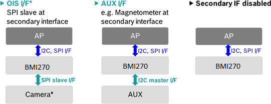
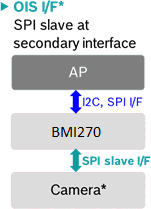
The secondary interface can operate as either an I2C master (auxiliary interface) for connecting an external sensor (e.g., BMM150 magnetometer for 9-DOF), or an SPI slave (OIS interface) for camera optical image stabilization. Only one mode can be active at a time.
OIS Interface
Provides pre-filtered gyroscope data at 6.4 kHz ODR and accelerometer data at 1.6 kHz ODR with minimum latency (group delay down to 680 us). Supports configurable low-pass filters with programmable cutoff frequencies. Available in SPI 3-wire and 4-wire modes.
Packages
| Package | Pins | Body Size | Height |
|---|---|---|---|
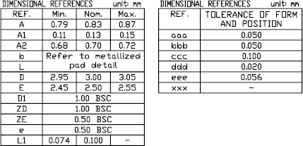
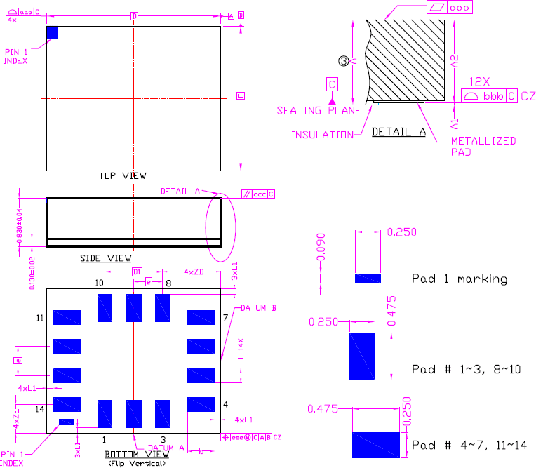
| LGA | 14 | 2.5 mm x 3.0 mm | 0.83 mm (typ) |
Package Dimensions
| Reference | Min | Nom | Max | Unit |
|---|---|---|---|---|
| A (height) | 0.79 | 0.83 | 0.87 | mm |
| A1 | 0.11 | 0.13 | 0.15 | mm |
| A2 | 0.68 | 0.70 | 0.72 | mm |
| D (length) | 2.95 | 3.00 | 3.05 | mm |
| E (width) | 2.45 | 2.50 | 2.55 | mm |
| D1 | — | 1.00 BSC | — | mm |
| e (pitch) | — | 0.50 BSC | — | mm |
| L1 | 0.074 | 0.100 | — | mm |
Software API
Initialization Sequence
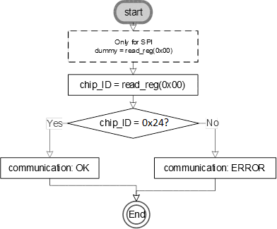
1. After power-up, read CHIP_ID register (0x00) to verify communication. Expected value: 0x24. For SPI, perform a dummy read first to switch the interface from default I2C to SPI mode. 2. Disable advanced power save: write 0x00 to PWR_CONF (0x7C), wait >= 450 us. 3. Prepare config load: write 0x00 to INIT_CTRL (0x59). 4. Burst-write the configuration file to INIT_DATA (0x5E). The config file is available at the Bosch BMI270 Sensor API GitHub repository. 5. Complete config load: write 0x01 to INIT_CTRL (0x59). 6. Wait >= 20 ms, then read INTERNAL_STATUS (0x21). Bit 0 = 1 indicates successful initialization.
Key Registers
| Address | Name | Description |
|---|---|---|
| 0x00 | CHIP_ID | Chip identification (reads 0x24) |
| 0x02 | ERR_REG | Error status register |
| 0x03 | STATUS | Sensor status flags |
| 0x04-0x17 | DATA_0..19 | Aux, accel, gyro sensor data |
| 0x18-0x1A | SENSORTIME | 24-bit sensor timestamp |
| 0x1C-0x1D | INT_STATUS | Interrupt status |
| 0x1E-0x1F | SC_OUT | Step counter output |
| 0x21 | INTERNAL_STATUS | Init status and error codes |
| 0x22-0x23 | TEMPERATURE | Temperature sensor data |
| 0x24-0x25 | FIFO_LENGTH | Current FIFO fill level |
| 0x26 | FIFO_DATA | FIFO data output |
| 0x40 | ACC_CONF | Accelerometer configuration (ODR, BW, filter) |
| 0x41 | ACC_RANGE | Accelerometer range selection |
| 0x42 | GYR_CONF | Gyroscope configuration (ODR, BW, filter, noise) |
| 0x43 | GYR_RANGE | Gyroscope range selection |
| 0x53 | INT1_IO_CTRL | INT1 pin electrical behavior |
| 0x54 | INT2_IO_CTRL | INT2 pin electrical behavior |
| 0x56-0x57 | INT1/2_MAP_FEAT | Feature interrupt mapping |
| 0x58 | INT_MAP_DATA | Data ready / FIFO interrupt mapping |
| 0x59 | INIT_CTRL | Config file load control |
| 0x7C | PWR_CONF | Power configuration (adv. power save, FIFO self-wake) |
| 0x7D | PWR_CTRL | Sensor enable control (accel, gyro, aux, temp) |
| 0x7E | CMD | Command register (soft reset, NVM prog, FIFO flush) |
FIFO
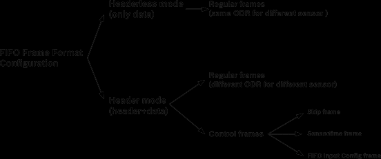
The 2 KB on-chip FIFO supports headerless mode (same ODR for all sensors) and header mode (different ODRs). Header mode includes regular frames, skip frames, sensortime frames, and FIFO input config frames. Watermark and full interrupts are available for efficient DMA-style data retrieval.
Offset and Sensitivity Compensation
- Accelerometer offset: Fast offset compensation (FOC) can be triggered via CMD register. User offsets stored in OFFSET_0 to OFFSET_2.
- Gyroscope offset: FOC compensates zero-rate offset. User offsets stored in OFFSET_3 to OFFSET_6.
- Gyroscope sensitivity (CRT): Component Retrimming reduces sensitivity error from +/-2% down to typ. +/-0.4% by running a built-in self-calibration routine.
Applications
- Fitness trackers, wristbands, and smart watches
- Earbuds and hearables (ankle bands, neck bands)
- Smart clothing and wearable textiles
- Augmented reality (AR) and virtual reality (VR) glasses and controllers
- Activity and context recognition systems
- Optical image stabilization (OIS) for wearable cameras
- Indoor navigation and dead reckoning
- Gesture-based user interfaces
Key Formulas
Accelerometer Data Conversion
acceleration_mg = raw_value / sensitivity_LSBperg * 1000Where sensitivity is 16384 LSB/g (+/-2g), 8192 LSB/g (+/-4g), 4096 LSB/g (+/-8g), or 2048 LSB/g (+/-16g).
Gyroscope Data Conversion
angular_rate_dps = raw_value / sensitivity_LSBperdpsWhere sensitivity is 262.144 LSB/dps (+/-125 dps), 131.072 (+/-250), 65.536 (+/-500), 32.768 (+/-1000), or 16.384 (+/-2000 dps).
Temperature Conversion
temperature_degC = (raw_value / 512) + 23I2C Address Selection
I2C_address = 0x68 (SDO pin = GND, default)
I2C_address = 0x69 (SDO pin = VDDIO)
Sensortime to Seconds
time_seconds = sensortime_raw * 39.0625e-6The 24-bit sensortime counter increments at 25.6 kHz (39.0625 us resolution).
Diagrams & Graphs (14)
**Source:** [Bosch Sensortec Datasheet (BST-BMI270-DS000-07)](https://www.bosch-sensortec.com/media/boschsensortec/downloads/datasheets/bst-bmi270-ds000.pdf)
**Manufacturer:** Bosch Sensortec
**Part Number:** BMI270
**Document:** BST-BMI270-DS000-07 — Rev 1.5, March 2023

## Description

The BMI270 is a highly integrated, ultra-low power inertial measurement unit (IMU) optimized for wearable applications. It combines precise acceleration and angular rate (gyroscopic) measurement with intelligent on-chip motion-triggered interrupt features. The device integrates a 16-bit digital triaxial accelerometer and a 16-bit digital triaxial gyroscope in a compact 2.5 x 3.0 mm LGA package. The BMI270 includes dedicated wearable gesture recognition features such as wrist wear wakeup, step counting, activity recognition, wrist gestures (flick in/out, push arm down, pivot up, wrist jiggle), and significant motion detection. It supports I2C (Fast-mode Plus) and SPI (up to 10 MHz) primary interfaces, an auxiliary I2C master interface for connecting external sensors like magnetometers, and an OIS SPI slave interface for camera optical image stabilization with up to 6.4 kHz ODR and sub-millisecond group delay. A built-in 2 KB FIFO buffer, hardware-synchronized sensor timestamps, and a comprehensive power management unit enable efficient battery-powered system designs.

## Key Specifications

| Parameter | Value |
| --- | --- |
| Supply Voltage (VDD) | 1.71V to 3.6V |
| I/O Supply Voltage (VDDIO) | 1.2V to 3.6V |
| Accelerometer Range | +/-2g, +/-4g, +/-8g, +/-16g |
| Gyroscope Range | +/-125, +/-250, +/-500, +/-1000, +/-2000 dps |
| Accelerometer ODR | 0.78 Hz to 1600 Hz |
| Gyroscope ODR | 25 Hz to 6400 Hz |
| Resolution | 16-bit (accel and gyro) |
| Current (Full ODR, Normal) | 685 uA typ |
| Current (A+G Suspend) | 3.5 uA typ |
| Current (Accel-only LP, 25 Hz) | 210 uA typ |
| Gyro Noise Density (Perf.) | 0.007 dps/sqrt(Hz) |
| Accel Noise Density | 0.16 mg/sqrt(Hz) |
| FIFO | 2 KB |
| Gyro Startup (Fast) | 2 ms |
| Interface | I2C (Fm+), SPI (10 MHz) |
| Package | LGA-14, 2.5 x 3.0 x 0.83 mm |
| Operating Temperature | -40 to +85 degC |
| Chip ID | 0x24 |

## Features

- 16-bit triaxial accelerometer with +/-2g/+/-4g/+/-8g/+/-16g selectable range
- 16-bit triaxial gyroscope with +/-125 to +/-2000 dps selectable range
- Ultra-low power consumption: 685 uA typical in full ODR normal mode
- Performance mode for gyroscope with noise as low as 0.007 dps/sqrt(Hz)
- Rapid gyroscope startup: 2 ms in fast-start mode
- Built-in power management unit (PMU) with advanced low-power modes
- 2 KB on-chip FIFO buffer for accel, gyro, timestamps, and auxiliary sensor data
- Hardware synchronization of accelerometer, gyroscope, and auxiliary sensor (< 1 us)
- Sensortime stamps for accurate host/sensor time synchronization (< 40 us)
- I2C Fast-mode Plus master interface hub for 1 auxiliary sensor (e.g., magnetometer)
- 10 MHz SPI slave OIS interface for camera stabilization with up to 6.4 kHz ODR
- Programmable low-pass filters: accel BW 5.5 to 740 Hz, gyro BW 11 to 751 Hz
- Fast offset and sensitivity error compensation (CRT reduces gyro error to typ. 0.4%)
- Wrist wear wakeup gesture detection
- Step counter and step detector (wrist-worn optimized)
- Activity and activity change recognition
- Significant motion, any-motion, and no-motion detection
- Wrist navigation gestures: flick in/out, push arm down, pivot up, wrist jiggle
- 2 independent programmable interrupt output pins
- RoHS compliant, halogen-free, lead-free

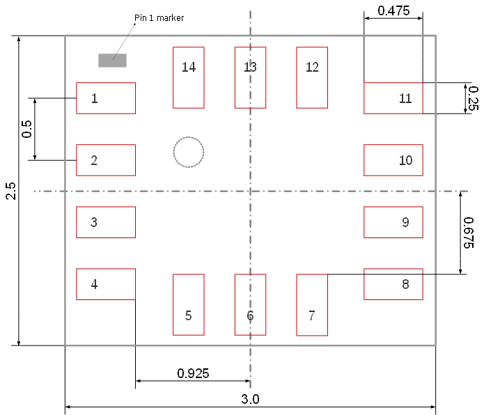
## Pin Configuration

| Pin | Name | Type | Description |
| --- | --- | --- | --- |
| 1 | SDO | Digital I/O | SPI serial data output (4-wire); I2C address bit-0 select |
| 2 | ASDx | Digital I/O | Secondary interface: Aux I2C SDA / OIS SPI SDI |
| 3 | ASCx | Digital I/O | Secondary interface: Aux I2C SCL / OIS SPI SCK |
| 4 | INT1 | Digital I/O | Interrupt output pin 1 (configurable) |
| 5 | VDDIO | Supply | Digital I/O supply voltage (1.2V to 3.6V) |
| 6 | GNDIO | Supply | Ground for digital I/O |
| 7 | GND | Supply | Ground for analog and digital core |
| 8 | VDD | Supply | Power supply for analog and digital core (1.71V to 3.6V) |
| 9 | INT2 | Digital I/O | Interrupt output pin 2 (configurable) |
| 10 | OCSB | Digital In | OIS SPI chip select (active low) |
| 11 | OSDO | Digital Out | OIS SPI serial data output |
| 12 | CSB | Digital In | SPI chip select (active low); I2C mode select |
| 13 | SCx | Digital In | SPI serial clock (SCK) / I2C serial clock (SCL) |
| 14 | SDx | Digital I/O | SPI serial data input (SDI) / I2C serial data (SDA) |

## Absolute Maximum Ratings

| Parameter | Condition | Min | Max | Unit |
| --- | --- | --- | --- | --- |
| Supply Voltage (VDD) | VDD Pin | -0.3 | 4 | V |
| Supply Voltage (VDDIO) | VDDIO Pin | -0.3 | 4 | V |
| Voltage at Logic Pin | Non-Supply Pin | -0.3 | VDDIO+0.3, <4 | V |
| Storage Temperature | <= 65% rel. humidity | -50 | +150 | degC |
| NVM Data Retention | T=85 degC, after 15 cycles | 10 | — | years |
| Mechanical Shock | Duration <= 200 us | — | 20,000 | g |
| Mechanical Shock | Duration <= 1.0 ms | — | 2,000 | g |
| Free Fall | Onto hard surfaces | — | 1.8 | m |
| ESD (HBM) | Any pin | — | 2 | kV |
| ESD (CDM) | — | — | 500 | V |
| ESD (MM) | JESD22A115C | — | 200 | V |

## Electrical Characteristics

### Accelerometer

| Parameter | Condition | Min | Typ | Max | Unit |
| --- | --- | --- | --- | --- | --- |
| Sensitivity (+/-2g) | TA=25 degC | — | 16384 | — | LSB/g |
| Sensitivity (+/-4g) | TA=25 degC | — | 8192 | — | LSB/g |
| Sensitivity (+/-8g) | TA=25 degC | — | 4096 | — | LSB/g |
| Sensitivity (+/-16g) | TA=25 degC | — | 2048 | — | LSB/g |
| Sensitivity Error | TA=25 degC, nominal VDD | — | — | +/-0.4 | % |
| Sensitivity Temp. Drift | Full TA range | — | 0.004 | — | %/K |
| Zero-g Offset | Soldered, over lifetime | — | — | +/-20 | mg |
| Zero-g Offset Temp. Drift | Full TA range | — | — | +/-0.25 | mg/K |
| Noise Density (Normal) | TA=25 degC, 8g range | — | 0.16 | — | mg/sqrt(Hz) |
| Noise RMS | BW=80 Hz, ODR=200 Hz, 8g | — | 1.51 | — | mg-rms |
| Nonlinearity | +/-2g range | — | 0.5 | — | %FS |
| ODR (Normal Mode) | — | 12.5 | — | 1600 | Hz |
| ODR (Low Power Mode) | — | 0.78 | — | 400 | Hz |
| Cross-Axis Sensitivity | Any two axes | — | 1 | — | % |
| Alignment Error | Relative to package | — | 0.5 | — | deg |
| Startup Time | Suspend to normal | — | 2 | — | ms |

### Gyroscope

| Parameter | Condition | Min | Typ | Max | Unit |
| --- | --- | --- | --- | --- | --- |
| Sensitivity (+/-2000 dps) | TA=25 degC | — | 16.384 | — | LSB/dps |
| Sensitivity (+/-1000 dps) | TA=25 degC | — | 32.768 | — | LSB/dps |
| Sensitivity (+/-500 dps) | TA=25 degC | — | 65.536 | — | LSB/dps |
| Sensitivity (+/-250 dps) | TA=25 degC | — | 131.072 | — | LSB/dps |
| Sensitivity (+/-125 dps) | TA=25 degC | — | 262.144 | — | LSB/dps |
| Sensitivity Error | TA=25 degC, nominal VDD | — | — | +/-2 | % |
| Sensitivity Error (after CRT) | TA=25 degC, after CRT | — | — | +/-0.4 | % |
| Sensitivity Temp. Drift | Full TA range | — | 0.02 | — | %/K |
| Zero-Rate Offset | Soldered, over lifetime | — | — | +/-0.5 | dps |
| Zero-Rate Offset Temp. Drift | Nominal VDD | — | — | +/-0.015 | dps/K |
| Noise Density (Performance) | TA=25 degC | — | 0.007 | — | dps/sqrt(Hz) |
| Noise Density (Normal) | TA=25 degC | — | 0.010 | — | dps/sqrt(Hz) |
| Noise RMS (Performance) | BW=74.6 Hz, ODR=200 Hz | — | 0.07 | — | dps-rms |
| Noise RMS (Normal) | BW=74.6 Hz, ODR=200 Hz | — | 0.09 | — | dps-rms |
| Nonlinearity | +/-250, +/-2000 dps | — | 0.01 | — | %FS |
| ODR (Normal/Performance) | — | 25 | — | 6400 | Hz |
| ODR (Low Power) | — | 25 | — | 100 | Hz |
| Cross-Axis Sensitivity | Any two axes | — | 0.2 | — | % |
| Alignment Error | Relative to package | — | 0.5 | — | deg |
| g-Sensitivity | Static acceleration | — | 0.1 | — | dps/g |
| Startup Time (Normal) | Suspend to normal | — | 45 | — | ms |
| Startup Time (Fast) | Fast start mode | — | 2 | — | ms |

### Temperature Sensor

| Parameter | Condition | Min | Typ | Max | Unit |
| --- | --- | --- | --- | --- | --- |
| ADC Resolution | — | — | 16 | — | bits |
| Measurement Range | — | -41 | — | 87 | degC |
| Output at 23 degC | — | — | 0 | — | LSB |
| Sensitivity | — | — | 512 | — | LSB/K |

## Power Consumption

| Mode | Condition | Typ | Unit |
| --- | --- | --- | --- |
| A+G Performance Mode | VDD=1.8V, TA=25 degC, ODRmax | 970 | uA |
| A+G Normal Mode | VDD=1.8V, TA=25 degC, ODRmax | 685 | uA |
| A+G Low Power Mode | VDD=1.8V, TA=25 degC, ODR 25 Hz | 420 | uA |
| Accel-only Normal Mode | VDD=1.8V, TA=25 degC, ODRmax | 210 | uA |
| Accel-only Low Power Mode | VDD=1.8V, TA=25 degC, ODR 25 Hz | — | uA |
| A+G Suspend Mode | VDD=1.8V, TA=25 degC | 3.5 | uA |
| Power-On Time | Supply on to I/F operational | 2 | ms |

## Communication Interface

### Primary Interface

The BMI270 supports I2C Fast-mode Plus and SPI (3-wire and 4-wire) as primary host interface. Protocol is auto-selected based on CSB pin state after power-up: if CSB is held at VDDIO, I2C mode is used; a rising edge on CSB switches to SPI mode.

| Parameter | Condition | Min | Typ | Max | Unit |
| --- | --- | --- | --- | --- | --- |
| SPI Clock Frequency | VDDIO >= 1.62V | — | — | 10 | MHz |
| I2C Address (SDO=GND) | Default | — | 0x68 | — | — |
| I2C Address (SDO=VDDIO) | Alternate | — | 0x69 | — | — |
| CSB Internal Pull-Up | To VDDIO | 75 | 100 | 140 | kOhm |
| Input Capacitance | — | — | 5 | — | pF |
| I2C Bus Load Capacitance | Max drive capability | — | 400 | — | pF |

### Secondary Interface

The secondary interface can operate as either an I2C master (auxiliary interface) for connecting an external sensor (e.g., BMM150 magnetometer for 9-DOF), or an SPI slave (OIS interface) for camera optical image stabilization. Only one mode can be active at a time.

### OIS Interface

Provides pre-filtered gyroscope data at 6.4 kHz ODR and accelerometer data at 1.6 kHz ODR with minimum latency (group delay down to 680 us). Supports configurable low-pass filters with programmable cutoff frequencies. Available in SPI 3-wire and 4-wire modes.

## Packages

| Package | Pins | Body Size | Height |
| --- | --- | --- | --- |
| LGA | 14 | 2.5 mm x 3.0 mm | 0.83 mm (typ) |

### Package Dimensions

| Reference | Min | Nom | Max | Unit |
| --- | --- | --- | --- | --- |
| A (height) | 0.79 | 0.83 | 0.87 | mm |
| A1 | 0.11 | 0.13 | 0.15 | mm |
| A2 | 0.68 | 0.70 | 0.72 | mm |
| D (length) | 2.95 | 3.00 | 3.05 | mm |
| E (width) | 2.45 | 2.50 | 2.55 | mm |
| D1 | — | 1.00 BSC | — | mm |
| e (pitch) | — | 0.50 BSC | — | mm |
| L1 | 0.074 | 0.100 | — | mm |

## Software API

### Initialization Sequence

1. After power-up, read CHIP_ID register (0x00) to verify communication. Expected value: **0x24**. For SPI, perform a dummy read first to switch the interface from default I2C to SPI mode.
2. Disable advanced power save: write `0x00` to PWR_CONF (0x7C), wait >= 450 us.
3. Prepare config load: write `0x00` to INIT_CTRL (0x59).
4. Burst-write the configuration file to INIT_DATA (0x5E). The config file is available at the [Bosch BMI270 Sensor API GitHub repository](https://github.com/BoschSensortec/BMI270-Sensor-API).
5. Complete config load: write `0x01` to INIT_CTRL (0x59).
6. Wait >= 20 ms, then read INTERNAL_STATUS (0x21). Bit 0 = 1 indicates successful initialization.

### Key Registers

| Address | Name | Description |
| --- | --- | --- |
| 0x00 | CHIP_ID | Chip identification (reads 0x24) |
| 0x02 | ERR_REG | Error status register |
| 0x03 | STATUS | Sensor status flags |
| 0x04-0x17 | DATA_0..19 | Aux, accel, gyro sensor data |
| 0x18-0x1A | SENSORTIME | 24-bit sensor timestamp |
| 0x1C-0x1D | INT_STATUS | Interrupt status |
| 0x1E-0x1F | SC_OUT | Step counter output |
| 0x21 | INTERNAL_STATUS | Init status and error codes |
| 0x22-0x23 | TEMPERATURE | Temperature sensor data |
| 0x24-0x25 | FIFO_LENGTH | Current FIFO fill level |
| 0x26 | FIFO_DATA | FIFO data output |
| 0x40 | ACC_CONF | Accelerometer configuration (ODR, BW, filter) |
| 0x41 | ACC_RANGE | Accelerometer range selection |
| 0x42 | GYR_CONF | Gyroscope configuration (ODR, BW, filter, noise) |
| 0x43 | GYR_RANGE | Gyroscope range selection |
| 0x53 | INT1_IO_CTRL | INT1 pin electrical behavior |
| 0x54 | INT2_IO_CTRL | INT2 pin electrical behavior |
| 0x56-0x57 | INT1/2_MAP_FEAT | Feature interrupt mapping |
| 0x58 | INT_MAP_DATA | Data ready / FIFO interrupt mapping |
| 0x59 | INIT_CTRL | Config file load control |
| 0x7C | PWR_CONF | Power configuration (adv. power save, FIFO self-wake) |
| 0x7D | PWR_CTRL | Sensor enable control (accel, gyro, aux, temp) |
| 0x7E | CMD | Command register (soft reset, NVM prog, FIFO flush) |

### FIFO

The 2 KB on-chip FIFO supports headerless mode (same ODR for all sensors) and header mode (different ODRs). Header mode includes regular frames, skip frames, sensortime frames, and FIFO input config frames. Watermark and full interrupts are available for efficient DMA-style data retrieval.

### Offset and Sensitivity Compensation

- **Accelerometer offset**: Fast offset compensation (FOC) can be triggered via CMD register. User offsets stored in OFFSET_0 to OFFSET_2.
- **Gyroscope offset**: FOC compensates zero-rate offset. User offsets stored in OFFSET_3 to OFFSET_6.
- **Gyroscope sensitivity (CRT)**: Component Retrimming reduces sensitivity error from +/-2% down to typ. +/-0.4% by running a built-in self-calibration routine.

## Applications

- Fitness trackers, wristbands, and smart watches
- Earbuds and hearables (ankle bands, neck bands)
- Smart clothing and wearable textiles
- Augmented reality (AR) and virtual reality (VR) glasses and controllers
- Activity and context recognition systems
- Optical image stabilization (OIS) for wearable cameras
- Indoor navigation and dead reckoning
- Gesture-based user interfaces

## Key Formulas

### Accelerometer Data Conversion
```
acceleration_mg = raw_value / sensitivity_LSBperg * 1000
```
Where sensitivity is 16384 LSB/g (+/-2g), 8192 LSB/g (+/-4g), 4096 LSB/g (+/-8g), or 2048 LSB/g (+/-16g).

### Gyroscope Data Conversion
```
angular_rate_dps = raw_value / sensitivity_LSBperdps
```
Where sensitivity is 262.144 LSB/dps (+/-125 dps), 131.072 (+/-250), 65.536 (+/-500), 32.768 (+/-1000), or 16.384 (+/-2000 dps).

### Temperature Conversion
```
temperature_degC = (raw_value / 512) + 23
```

### I2C Address Selection
```
I2C_address = 0x68 (SDO pin = GND, default)
I2C_address = 0x69 (SDO pin = VDDIO)
```

### Sensortime to Seconds
```
time_seconds = sensortime_raw * 39.0625e-6
```
The 24-bit sensortime counter increments at 25.6 kHz (39.0625 us resolution).
Sub-Skills
What are Sub-Skills?
Sub-skills are community-contributed AI skill extensions for this component.
They teach AI assistants about specific tools, configurators, or workflows.
Examples:
- A manufacturer’s configuration tool for a motor controller
- A community-written design guide for an amplifier circuit
- An automated test/validation script for a sensor module
How to add one: Click Add Sub-Skill, provide the URL
to your skill and a brief description. Submissions are reviewed by the Adom team
before going live.
Sub-skills are community-contributed AI skill extensions for this component. They teach AI assistants about specific tools, configurators, or workflows.
Examples:
- A manufacturer’s configuration tool for a motor controller
- A community-written design guide for an amplifier circuit
- An automated test/validation script for a sensor module
How to add one: Click Add Sub-Skill, provide the URL to your skill and a brief description. Submissions are reviewed by the Adom team before going live.
No sub-skills yet. Be the first to contribute one!