BMA456
Bosch Sensortec BMA456. 16-bit triaxial MEMS accelerometer for wearables. +/-2g to +/-16g range, 150uA performance / 3.5uA suspend, SPI/I2C, 1KB FIFO, step counter, LGA-12 2x2mm. Standardized datasheet with 10 extracted diagrams.
Paste this into Claude Code (VS Code panel, Adom editor, or terminal) to install:
Search the Adom Wiki for the datasheet "BMA456" (slug: bma456) at https://wiki-ufypy5dpx93o.adom.cloud/wiki/datasheets/bma456. Download the standardized markdown and extracted diagram images into my project's datasheets/bma456/ directory. Show me the key specifications and pin configuration.
Source: Bosch Sensortec Datasheet (BST-BMA456-DS000-09) Manufacturer: Bosch Sensortec Part Number: BMA456 Document: BST-BMA456-DS000-09 — Rev 3.6, March 2026
Description
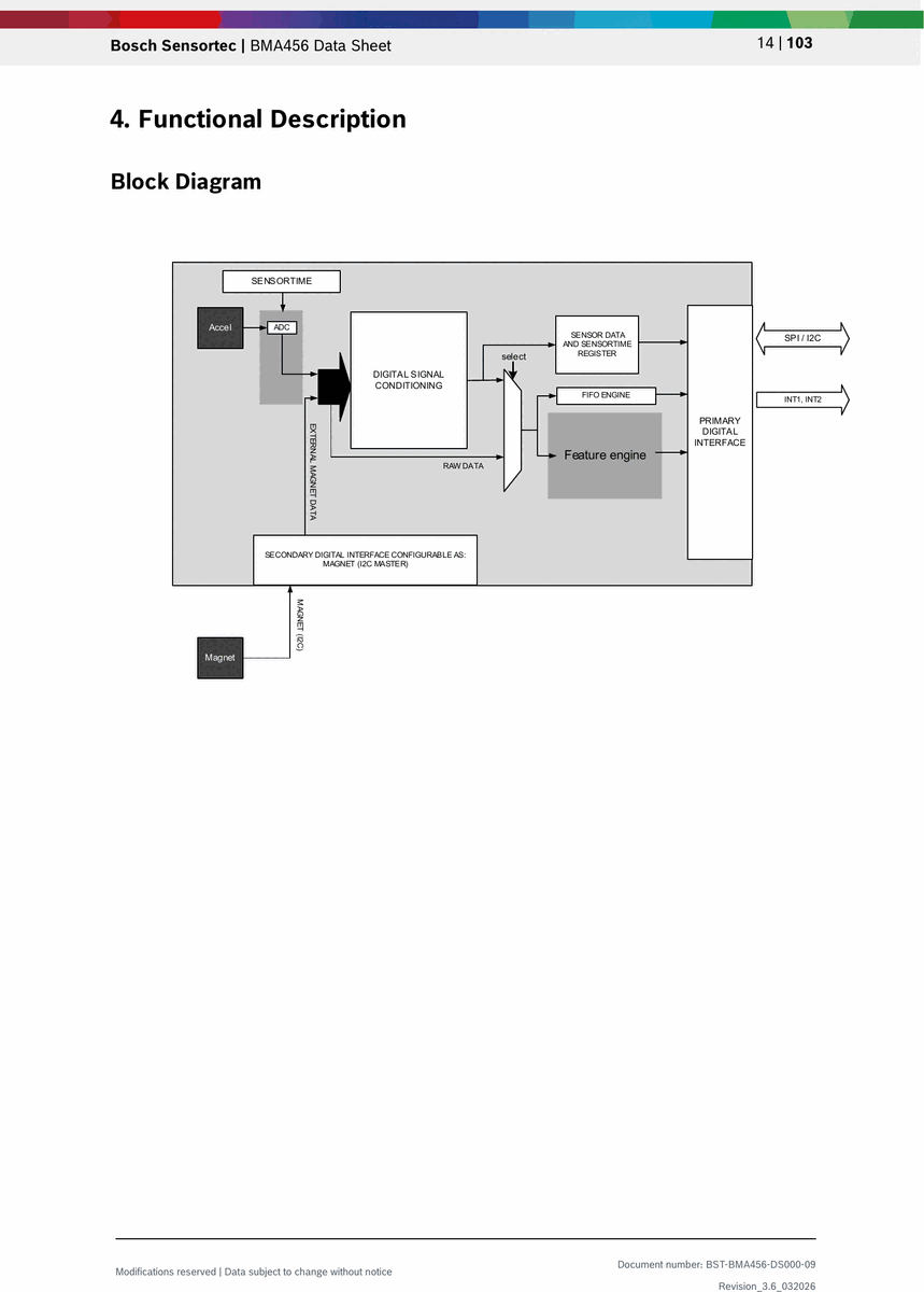
The BMA456 is a 16-bit, digital, triaxial acceleration sensor with intelligent on-chip motion-triggered interrupt features optimized for wearable applications. It combines ultra-low power consumption with a small 2mm x 2mm LGA footprint and a programmable feature engine that supports step counting, activity recognition, and wrist gestures without burdening the host processor. The sensor communicates over SPI (3-wire and 4-wire) or I2C and includes a secondary auxiliary I2C master interface for connecting an external magnetometer with synchronized data readout. An integrated 1KB FIFO buffers sensor data to minimize host wake-ups, enabling aggressive power management in battery-constrained wearable and hearable devices.
Key Specifications
Features
- • 16-bit digital triaxial accelerometer with selectable ranges of +/-2g, +/-4g, +/-8g, +/-16g
- • Ultra-low power: 3.5 uA suspend, 14 uA low-power (50 Hz), 150 uA performance mode
- • Small LGA-12 package: 2.0mm x 2.0mm x 0.65mm footprint
- • Programmable on-chip feature engine with step counter, activity recognition, and wrist gestures
- • Integrated 1 KB FIFO with watermark interrupt for efficient host power management
- • SPI (3-wire and 4-wire) and I2C primary digital interface
- • Secondary auxiliary I2C master interface for external magnetometer hub with data synchronization
- • Configurable low-pass filter bandwidths from <8 Hz to 684 Hz
- • Two configurable interrupt output pins (INT1, INT2) with latched or non-latched mode
- • On-chip temperature sensor
- • 24-bit sensor time counter (39.25 us resolution)
- • Self-test and inline offset calibration capability
- • Non-volatile memory (NVM) with 15 write cycles for offset storage
- • Mechanical shock resistance up to 10,000g (200 us duration)
- • RoHS compliant, halogen-free
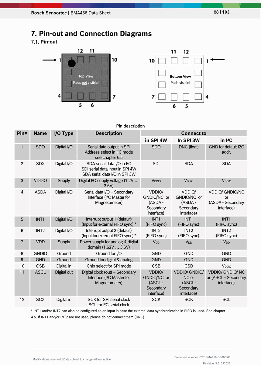
Pin Configuration
Source: Bosch Sensortec Datasheet (BST-BMA456-DS000-09) Manufacturer: Bosch Sensortec Part Number: BMA456 Document: BST-BMA456-DS000-09 — Rev 3.6, March 2026
Absolute Maximum Ratings
| Parameter | Condition | Min | Max | Unit |
|---|---|---|---|---|
| Voltage at VDD Pin | -- | -0.3 | 4 | V |
| Voltage at VDDIO Pin | -- | -0.3 | 4 | V |
| Voltage at any Logic Pin | Non-supply pin | -0.3 | VDDIO+0.3 (<4V) | V |
| Passive Storage Temperature | <=65% rel. humidity | -50 | +150 | deg C |
| NVM Data Retention | T=85 deg C, after 15 cycles | 10 | -- | years |
| Mechanical Shock | Duration <=200 us | -- | 10,000 | g |
| Mechanical Shock | Duration <=1.0 ms | -- | 2,000 | g |
| Free Fall | Onto hard surfaces | -- | 1.8 | m |
| ESD (HBM) | Any pin | -- | 2 | kV |
| ESD (CDM) | Any pin | -- | 500 | V |
| ESD (MM) | Any pin | -- | 200 | V |
Electrical Characteristics
| Parameter | Symbol | Condition | Min | Typ | Max | Unit |
|---|---|---|---|---|---|---|
| Supply Voltage (Internal) | VDD | -- | 1.62 | 1.8 | 3.6 | V |
| Supply Voltage (I/O) | VDDIO | -- | 1.2 | 1.8 | 3.6 | V |
| Input Voltage Low | VIL | SPI and I2C | -- | -- | 0.3 x VDDIO | V |
| Input Voltage High | VIH | SPI and I2C | 0.7 x VDDIO | -- | -- | V |
| Output Voltage Low | VOL | VDDIO>=1.62V, IOL<=2mA | -- | -- | 0.2 x VDDIO | V |
| Output Voltage High | VOH | VDDIO>=1.62V, IOH<=2mA | 0.8 x VDDIO | -- | -- | V |
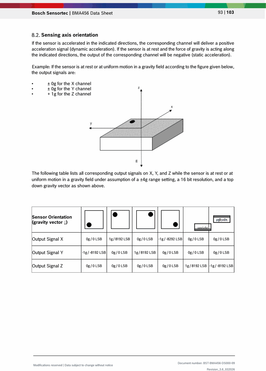
| Sensitivity (+/-2g) | S2g | TA=25 deg C | -- | 16384 | -- | LSB/g |
| Sensitivity (+/-4g) | S4g | TA=25 deg C | -- | 8192 | -- | LSB/g |
| Sensitivity (+/-8g) | S8g | TA=25 deg C | -- | 4096 | -- | LSB/g |
| Sensitivity (+/-16g) | S16g | TA=25 deg C | -- | 2048 | -- | LSB/g |
| Sensitivity Temperature Drift | TCS | -- | -- | +/-0.005 | -- | %/K |
| Zero-g Offset | -- | Nominal, 25 deg C, +/-4g | -- | -- | +/-20 | mg |
| Zero-g Offset Temp Drift (X/Y) | TCO | -- | -- | +/-0.2 | -- | mg/K |
| Zero-g Offset Temp Drift (Z) | TCO | -- | -- | +/-0.35 | -- | mg/K |
| Nonlinearity | NL | Nominal, 25 deg C, +/-4g | -- | -- | +/-0.5 | %FS |
| Output Noise Density | ndens | Nominal, 25 deg C, +/-4g | -- | 120 | -- | ug/sqrt(Hz) |
| Cross Axis Sensitivity | S | Between any two axes | -- | -- | +/-0.5 | % |
| Alignment Error | EA | Relative to package outline | -- | -- | +/-0.5 | deg |
Power Consumption
| Parameter | Symbol | Condition | Typ | Unit |
|---|---|---|---|---|
| Performance Mode | IDD | Nominal VDD and VDDIO, 25 deg C, +/-4g | 150 | uA |
| Low-Power Mode | IDDlp1 | Nominal VDD and VDDIO, 25 deg C, 50 Hz ODR | 14 | uA |
| Suspend Mode | IDDsum | Nominal VDD and VDDIO, 25 deg C | 3.5 | uA |
| Power-Up Time | ts_up | -- | 1 | ms |
Communication Interface
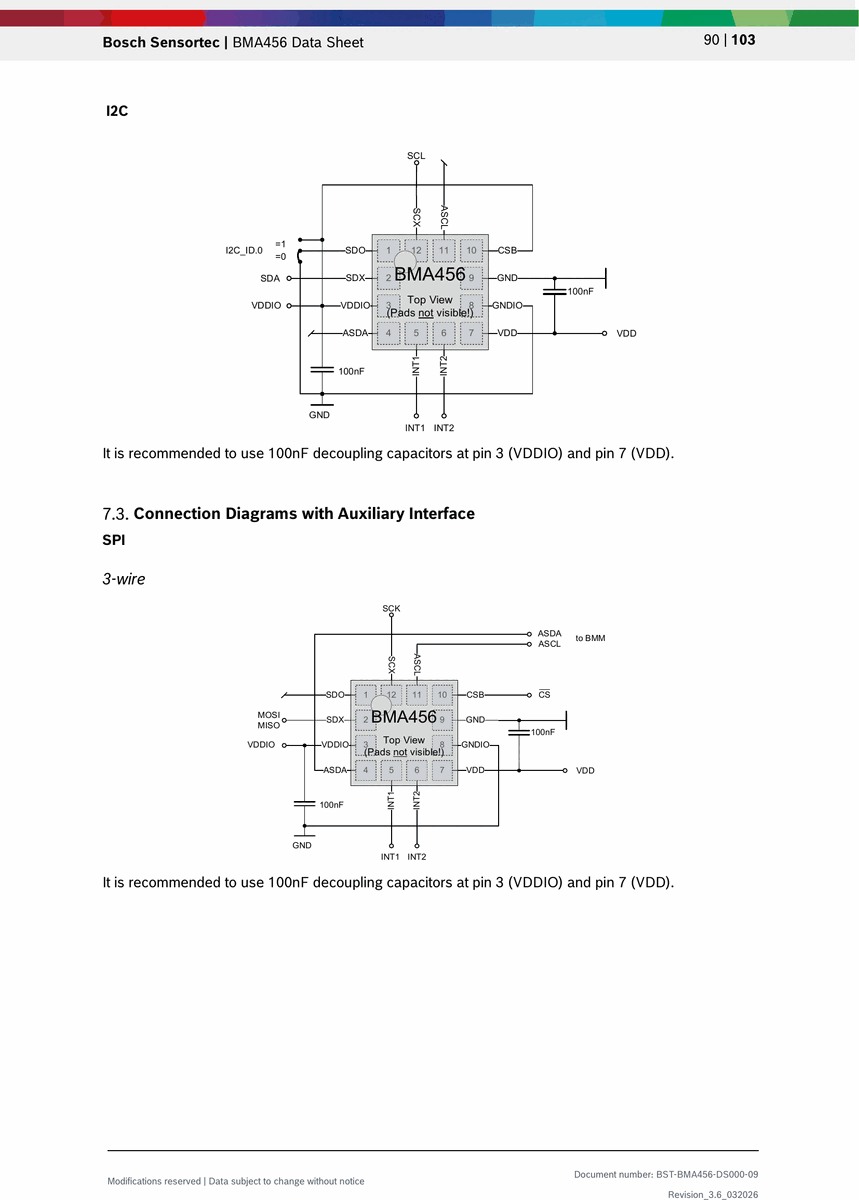
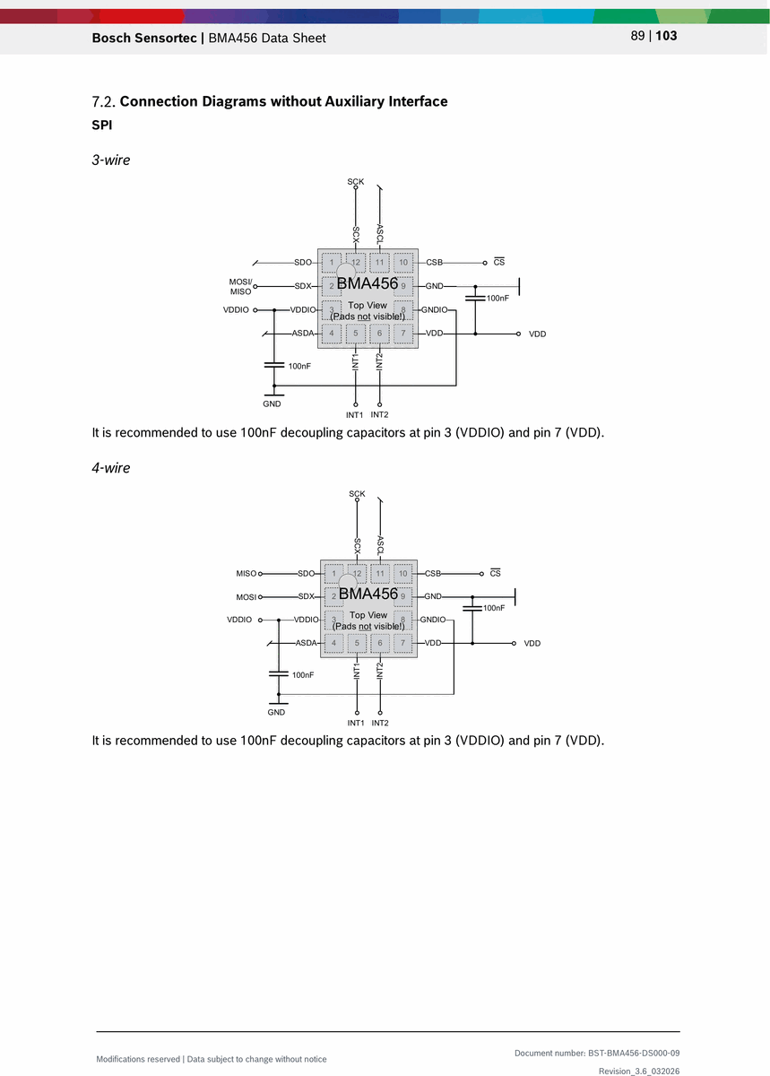
The BMA456 supports SPI (3-wire and 4-wire) and I2C digital interfaces on the primary bus, selected at power-up based on the CSB pin state. SPI mode supports clock rates up to 10 MHz. I2C mode supports standard (100 kHz) and fast (400 kHz) modes with a 7-bit device address of 0x18 (SDO=GND) or 0x19 (SDO=VDDIO).
A secondary auxiliary I2C master interface (pins ASDA, ASCL) enables direct connection to an external magnetometer. The auxiliary interface performs automatic periodic reads from the external sensor and stores data in the BMA456 data registers, enabling synchronized accelerometer-magnetometer readout without host processor intervention.
| Parameter | Value |
|---|---|
| Primary Interface | SPI (3-wire, 4-wire) and I2C |
| SPI Clock | Up to 10 MHz |
| I2C Modes | Standard (100 kHz), Fast (400 kHz) |
| I2C Address | 0x18 (SDO=GND) or 0x19 (SDO=VDDIO) |
| Auxiliary Interface | I2C master for external magnetometer |
| Interrupt Pins | 2 (INT1, INT2), configurable push-pull/open-drain, active-high/low |
Packages
| Parameter | Value |
|---|---|
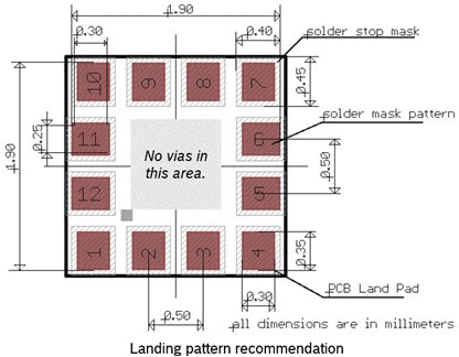
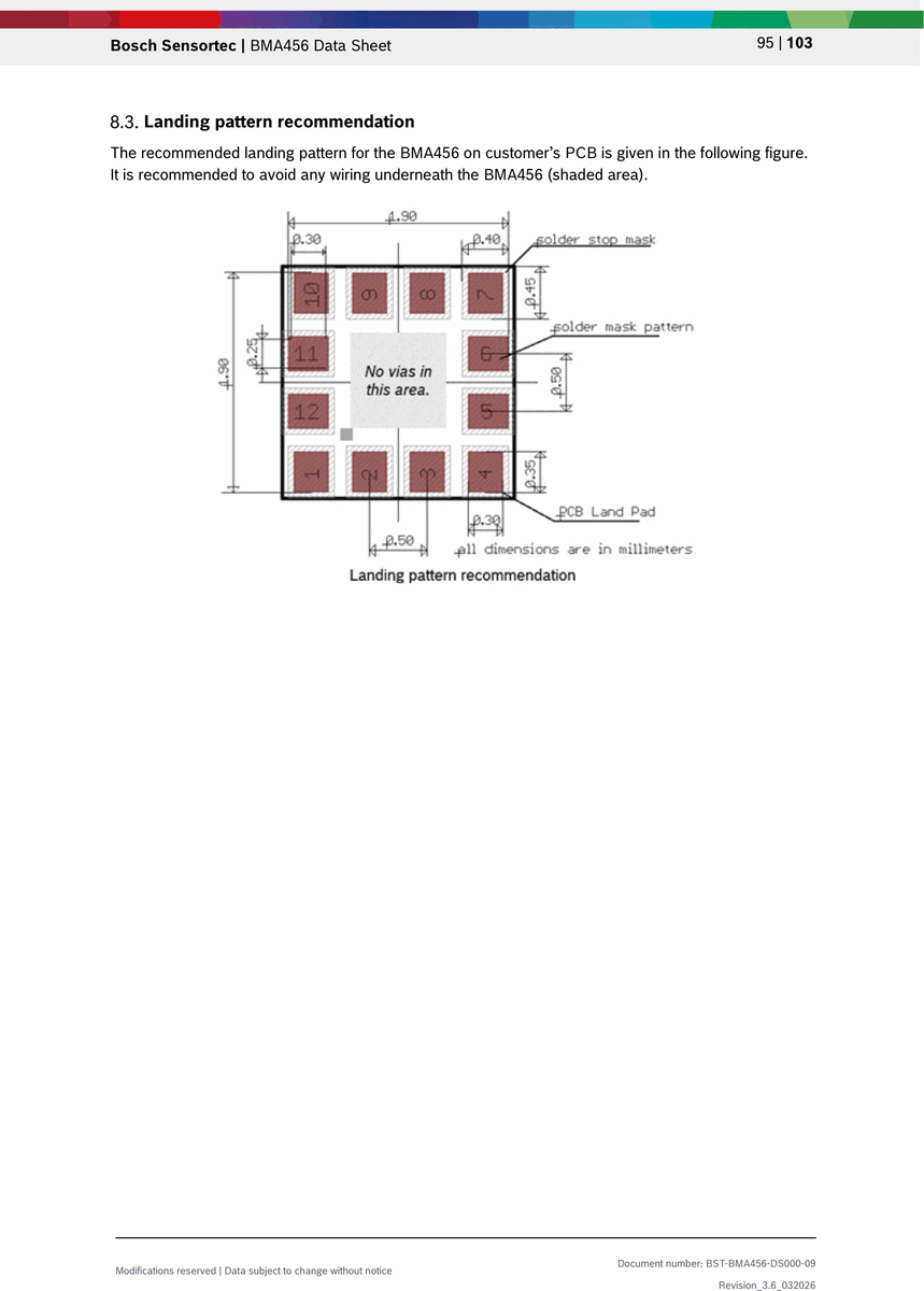
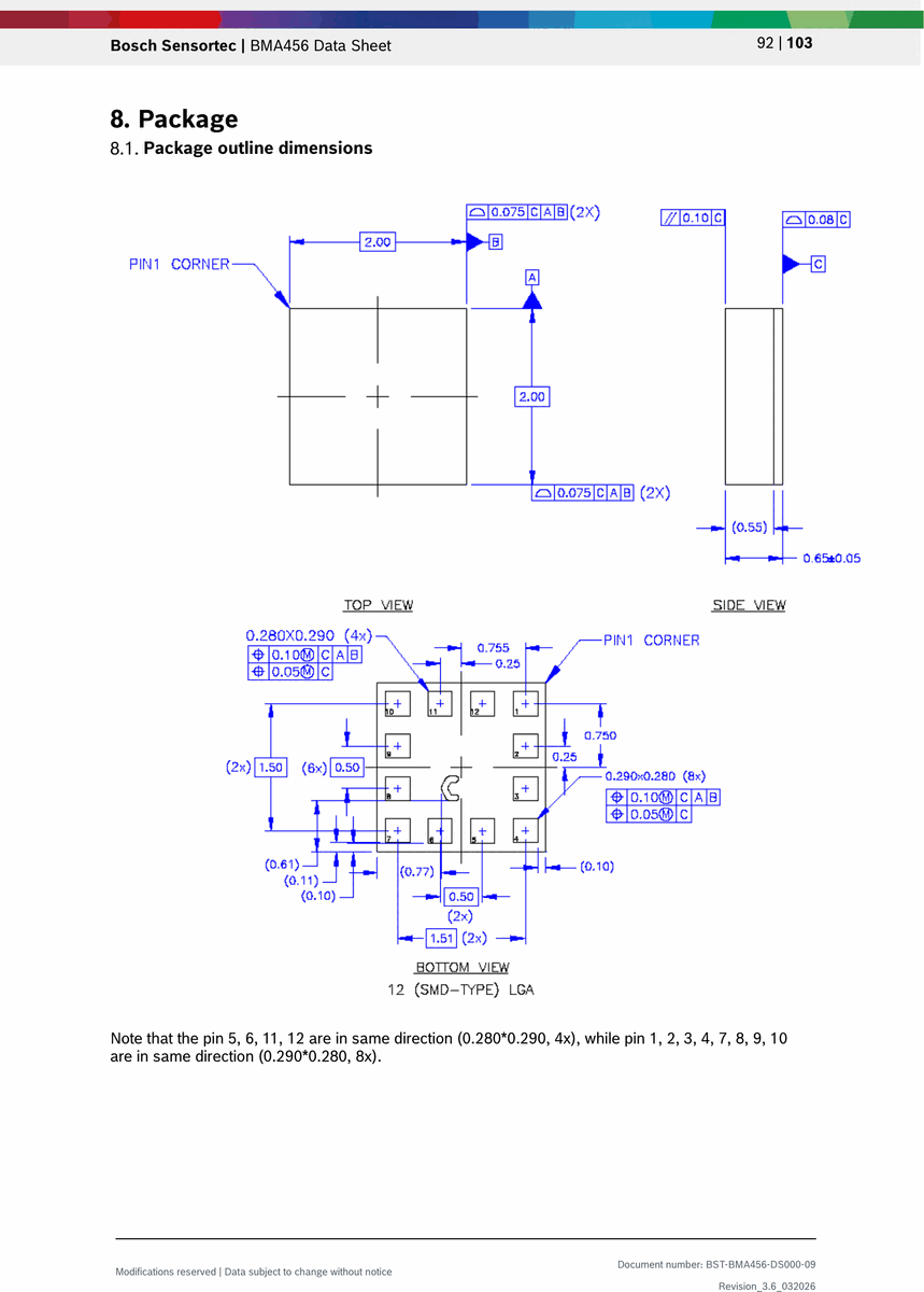
| Package Type | LGA (Land Grid Array), 12-pin, SMD |
| Body Size | 2.0mm x 2.0mm |
| Height | 0.65mm |
| Pad Pitch | See package drawing |
| Pin Count | 12 |
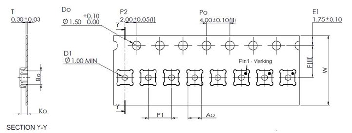
| Marking | 3-digit alphanumeric counter ID with pin 1 dot |
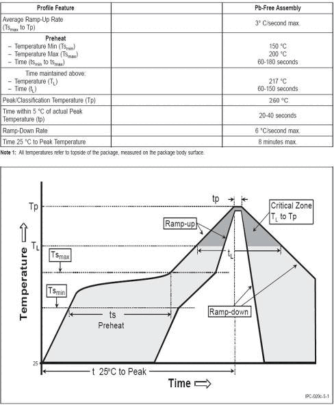
| Soldering | Pb-free reflow, peak 260 deg C max |
| Moisture Sensitivity | MSL 1 (unlimited floor life) |
| RoHS | Compliant, halogen-free |
Software API
The BMA456 requires a firmware initialization sequence after every power-on reset or soft-reset. Bosch Sensortec provides an official C driver (BMA4xy Sensor API) available on their website and GitHub.
Initialization sequence: 1. Power up and wait 1 ms 2. Disable advanced power save: write 0x00 to PWR_CONF (0x7C) 3. Wait 450 us 4. Write 0x00 to INIT_CTRL (0x59) 5. Burst write configuration file to FEATURES_IN (0x5E) 6. Write 0x01 to INIT_CTRL (0x59) 7. Wait up to 150 ms, verify INTERNAL_STATUS (0x2A) bit[4:0] = 0x01
Key registers:
CHIP_ID(0x00): reads 0x16ACC_CONF(0x40): accelerometer ODR, bandwidth, performance modeACC_RANGE(0x41): acceleration range selectionPWR_CONF(0x7C): advanced power save, FIFO self-wakeupPWR_CTRL(0x7D): accelerometer and auxiliary enableINT1_IO_CTRL(0x53) /INT2_IO_CTRL(0x54): interrupt pin configurationFIFO_CONFIG_0/1(0x48/0x49): FIFO mode and enableCMD(0x7E): soft-reset (write 0xB6), FIFO flush (write 0xB0)
Feature engine functions (via configuration file):
- Step counter with watermark interrupt
- Step detector (single step event)
- Activity recognition (still, walking, running)
- Wrist wear wakeup gesture
- Any-motion / no-motion detection
- Single/double tap detection
Applications
- Wearable fitness trackers and smartwatches
- Hearable devices (wireless earbuds)
- Plug-and-play step counter with watermark functionality
- Activity tracking and recognition (still, walking, running)
- Power management for wearable/hearable applications (display on/off, profile switching)
- User interface without hardware buttons (gesture control)
- E-compass tilt compensation with magnetometer data synchronization
- High-performance angle measurement
- Height-constrained applications requiring ultra-thin sensors
Key Formulas
Acceleration Conversion
acceleration_mg = raw_value / sensitivity_LSBperG * 1000

Sensitivity: 16384 LSB/g (+/-2g), 8192 LSB/g (+/-4g), 4096 LSB/g (+/-8g), 2048 LSB/g (+/-16g)
Sensor Time
time_seconds = SENSORTIME_value * 39.0625e-6

24-bit counter, resolution = 39.0625 us per LSB
Rollover period = 2^24 * 39.0625 us = ~655.36 seconds
Temperature
temperature_degC = (TEMPERATURE_register * 1) + 23

Range: -40 to +85 deg C, Resolution: 1 K/LSB, Offset: ~1 K
Output Data Rate (ODR)
ODR_Hz = 100 / (2^(8 - acc_odr))

acc_odr values: 0x01 (0.78 Hz) to 0x0C (1600 Hz)
Performance mode: 12.5 Hz to 1600 Hz
Low-power mode: 0.78 Hz to 400 Hz
FIFO Capacity
max_frames = 1024 / frame_length_bytes

Accel-only frame: 7 bytes (1 header + 6 data)
Accel+Aux frame: 13 bytes (1 header + 6 accel + 6 aux)
Accel+Time frame: 11 bytes (1 header + 6 data + 4 sensortime)
Diagrams & Graphs (10)

**Source:** [Bosch Sensortec Datasheet (BST-BMA456-DS000-09)](https://www.bosch-sensortec.com/media/boschsensortec/downloads/datasheets/bst-bma456-ds000.pdf)
**Manufacturer:** Bosch Sensortec
**Part Number:** BMA456
**Document:** BST-BMA456-DS000-09 — Rev 3.6, March 2026

## Description

The BMA456 is a 16-bit, digital, triaxial acceleration sensor with intelligent on-chip motion-triggered interrupt features optimized for wearable applications. It combines ultra-low power consumption with a small 2mm x 2mm LGA footprint and a programmable feature engine that supports step counting, activity recognition, and wrist gestures without burdening the host processor. The sensor communicates over SPI (3-wire and 4-wire) or I2C and includes a secondary auxiliary I2C master interface for connecting an external magnetometer with synchronized data readout. An integrated 1KB FIFO buffers sensor data to minimize host wake-ups, enabling aggressive power management in battery-constrained wearable and hearable devices.

## Key Specifications

| Parameter | Value |
| --- | --- |
| Acceleration Range | +/-2g / +/-4g / +/-8g / +/-16g (selectable) |
| Resolution | 16-bit |
| Supply Voltage (VDD) | 1.62V to 3.6V |
| Supply Voltage (VDDIO) | 1.2V to 3.6V |
| Current (Performance Mode) | 150 uA typ |
| Current (Low-Power Mode) | 14 uA typ (50 Hz ODR) |
| Current (Suspend Mode) | 3.5 uA typ |
| Output Data Rate | 0.78 Hz to 1600 Hz |
| Noise Density | 120 ug/sqrt(Hz) |
| FIFO | 1 KB integrated |
| Interface | SPI (3/4-wire), I2C, auxiliary I2C master |
| Package | LGA-12, 2.0mm x 2.0mm x 0.65mm |
| Operating Temperature | -40 to +85 deg C |
| Chip ID | 0x16 |

## Features

- 16-bit digital triaxial accelerometer with selectable ranges of +/-2g, +/-4g, +/-8g, +/-16g
- Ultra-low power: 3.5 uA suspend, 14 uA low-power (50 Hz), 150 uA performance mode
- Small LGA-12 package: 2.0mm x 2.0mm x 0.65mm footprint
- Programmable on-chip feature engine with step counter, activity recognition, and wrist gestures
- Integrated 1 KB FIFO with watermark interrupt for efficient host power management
- SPI (3-wire and 4-wire) and I2C primary digital interface
- Secondary auxiliary I2C master interface for external magnetometer hub with data synchronization
- Configurable low-pass filter bandwidths from <8 Hz to 684 Hz
- Two configurable interrupt output pins (INT1, INT2) with latched or non-latched mode
- On-chip temperature sensor
- 24-bit sensor time counter (39.25 us resolution)
- Self-test and inline offset calibration capability
- Non-volatile memory (NVM) with 15 write cycles for offset storage
- Mechanical shock resistance up to 10,000g (200 us duration)
- RoHS compliant, halogen-free

## Pin Configuration

| Pin | Name | Type | Description |
| --- | --- | --- | --- |
| 1 | SDO | Digital I/O | Serial data output in SPI; address select in I2C mode (GND = default address) |
| 2 | SDX | Digital I/O | SDA serial data I/O in I2C; SDI serial data input in SPI 4W; SDA I/O in SPI 3W |
| 3 | VDDIO | Supply | Digital I/O supply voltage (1.2V to 3.6V) |
| 4 | ASDA | Digital I/O | Serial data I/O for secondary auxiliary interface (I2C master for magnetometer) |
| 5 | INT1 | Digital I/O | Interrupt output 1 (default); input for external FIFO sync |
| 6 | INT2 | Digital I/O | Interrupt output 2 (default); input for external FIFO sync |
| 7 | VDD | Supply | Power supply for analog and digital domain (1.62V to 3.6V) |
| 8 | GNDIO | Ground | Ground for I/O |
| 9 | GND | Ground | Ground for digital and analog |
| 10 | CSB | Digital In | Chip select for SPI mode (active low); tie to VDDIO for I2C mode |
| 11 | ASCL | Digital Out | Serial clock for secondary auxiliary interface (I2C master for magnetometer) |
| 12 | SCX | Digital In | SCK for SPI serial clock; SCL for I2C serial clock |

## Absolute Maximum Ratings

| Parameter | Condition | Min | Max | Unit |
| --- | --- | --- | --- | --- |
| Voltage at VDD Pin | -- | -0.3 | 4 | V |
| Voltage at VDDIO Pin | -- | -0.3 | 4 | V |
| Voltage at any Logic Pin | Non-supply pin | -0.3 | VDDIO+0.3 (<4V) | V |
| Passive Storage Temperature | <=65% rel. humidity | -50 | +150 | deg C |
| NVM Data Retention | T=85 deg C, after 15 cycles | 10 | -- | years |
| Mechanical Shock | Duration <=200 us | -- | 10,000 | g |
| Mechanical Shock | Duration <=1.0 ms | -- | 2,000 | g |
| Free Fall | Onto hard surfaces | -- | 1.8 | m |
| ESD (HBM) | Any pin | -- | 2 | kV |
| ESD (CDM) | Any pin | -- | 500 | V |
| ESD (MM) | Any pin | -- | 200 | V |

## Electrical Characteristics

| Parameter | Symbol | Condition | Min | Typ | Max | Unit |
| --- | --- | --- | --- | --- | --- | --- |
| Supply Voltage (Internal) | VDD | -- | 1.62 | 1.8 | 3.6 | V |
| Supply Voltage (I/O) | VDDIO | -- | 1.2 | 1.8 | 3.6 | V |
| Input Voltage Low | VIL | SPI and I2C | -- | -- | 0.3 x VDDIO | V |
| Input Voltage High | VIH | SPI and I2C | 0.7 x VDDIO | -- | -- | V |
| Output Voltage Low | VOL | VDDIO>=1.62V, IOL<=2mA | -- | -- | 0.2 x VDDIO | V |
| Output Voltage High | VOH | VDDIO>=1.62V, IOH<=2mA | 0.8 x VDDIO | -- | -- | V |
| Sensitivity (+/-2g) | S2g | TA=25 deg C | -- | 16384 | -- | LSB/g |
| Sensitivity (+/-4g) | S4g | TA=25 deg C | -- | 8192 | -- | LSB/g |
| Sensitivity (+/-8g) | S8g | TA=25 deg C | -- | 4096 | -- | LSB/g |
| Sensitivity (+/-16g) | S16g | TA=25 deg C | -- | 2048 | -- | LSB/g |
| Sensitivity Temperature Drift | TCS | -- | -- | +/-0.005 | -- | %/K |
| Zero-g Offset | -- | Nominal, 25 deg C, +/-4g | -- | -- | +/-20 | mg |
| Zero-g Offset Temp Drift (X/Y) | TCO | -- | -- | +/-0.2 | -- | mg/K |
| Zero-g Offset Temp Drift (Z) | TCO | -- | -- | +/-0.35 | -- | mg/K |
| Nonlinearity | NL | Nominal, 25 deg C, +/-4g | -- | -- | +/-0.5 | %FS |
| Output Noise Density | ndens | Nominal, 25 deg C, +/-4g | -- | 120 | -- | ug/sqrt(Hz) |
| Cross Axis Sensitivity | S | Between any two axes | -- | -- | +/-0.5 | % |
| Alignment Error | EA | Relative to package outline | -- | -- | +/-0.5 | deg |

## Power Consumption

| Parameter | Symbol | Condition | Typ | Unit |
| --- | --- | --- | --- | --- |
| Performance Mode | IDD | Nominal VDD and VDDIO, 25 deg C, +/-4g | 150 | uA |
| Low-Power Mode | IDDlp1 | Nominal VDD and VDDIO, 25 deg C, 50 Hz ODR | 14 | uA |
| Suspend Mode | IDDsum | Nominal VDD and VDDIO, 25 deg C | 3.5 | uA |
| Power-Up Time | ts_up | -- | 1 | ms |

## Communication Interface

The BMA456 supports SPI (3-wire and 4-wire) and I2C digital interfaces on the primary bus, selected at power-up based on the CSB pin state. SPI mode supports clock rates up to 10 MHz. I2C mode supports standard (100 kHz) and fast (400 kHz) modes with a 7-bit device address of `0x18` (SDO=GND) or `0x19` (SDO=VDDIO).

A secondary auxiliary I2C master interface (pins ASDA, ASCL) enables direct connection to an external magnetometer. The auxiliary interface performs automatic periodic reads from the external sensor and stores data in the BMA456 data registers, enabling synchronized accelerometer-magnetometer readout without host processor intervention.

| Parameter | Value |
| --- | --- |
| Primary Interface | SPI (3-wire, 4-wire) and I2C |
| SPI Clock | Up to 10 MHz |
| I2C Modes | Standard (100 kHz), Fast (400 kHz) |
| I2C Address | 0x18 (SDO=GND) or 0x19 (SDO=VDDIO) |
| Auxiliary Interface | I2C master for external magnetometer |
| Interrupt Pins | 2 (INT1, INT2), configurable push-pull/open-drain, active-high/low |

## Packages

| Parameter | Value |
| --- | --- |
| Package Type | LGA (Land Grid Array), 12-pin, SMD |
| Body Size | 2.0mm x 2.0mm |
| Height | 0.65mm |
| Pad Pitch | See package drawing |
| Pin Count | 12 |
| Marking | 3-digit alphanumeric counter ID with pin 1 dot |
| Soldering | Pb-free reflow, peak 260 deg C max |
| Moisture Sensitivity | MSL 1 (unlimited floor life) |
| RoHS | Compliant, halogen-free |

## Software API

The BMA456 requires a firmware initialization sequence after every power-on reset or soft-reset. Bosch Sensortec provides an official C driver (BMA4xy Sensor API) available on their website and GitHub.

**Initialization sequence:**
1. Power up and wait 1 ms
2. Disable advanced power save: write `0x00` to `PWR_CONF` (0x7C)
3. Wait 450 us
4. Write `0x00` to `INIT_CTRL` (0x59)
5. Burst write configuration file to `FEATURES_IN` (0x5E)
6. Write `0x01` to `INIT_CTRL` (0x59)
7. Wait up to 150 ms, verify `INTERNAL_STATUS` (0x2A) bit[4:0] = 0x01

**Key registers:**
- `CHIP_ID` (0x00): reads 0x16
- `ACC_CONF` (0x40): accelerometer ODR, bandwidth, performance mode
- `ACC_RANGE` (0x41): acceleration range selection
- `PWR_CONF` (0x7C): advanced power save, FIFO self-wakeup
- `PWR_CTRL` (0x7D): accelerometer and auxiliary enable
- `INT1_IO_CTRL` (0x53) / `INT2_IO_CTRL` (0x54): interrupt pin configuration
- `FIFO_CONFIG_0/1` (0x48/0x49): FIFO mode and enable
- `CMD` (0x7E): soft-reset (write 0xB6), FIFO flush (write 0xB0)

**Feature engine functions** (via configuration file):
- Step counter with watermark interrupt
- Step detector (single step event)
- Activity recognition (still, walking, running)
- Wrist wear wakeup gesture
- Any-motion / no-motion detection
- Single/double tap detection

## Applications

- Wearable fitness trackers and smartwatches
- Hearable devices (wireless earbuds)
- Plug-and-play step counter with watermark functionality
- Activity tracking and recognition (still, walking, running)
- Power management for wearable/hearable applications (display on/off, profile switching)
- User interface without hardware buttons (gesture control)
- E-compass tilt compensation with magnetometer data synchronization
- High-performance angle measurement
- Height-constrained applications requiring ultra-thin sensors

## Key Formulas

### Acceleration Conversion
```
acceleration_mg = raw_value / sensitivity_LSBperG * 1000

Sensitivity: 16384 LSB/g (+/-2g), 8192 LSB/g (+/-4g), 4096 LSB/g (+/-8g), 2048 LSB/g (+/-16g)
```

### Sensor Time
```
time_seconds = SENSORTIME_value * 39.0625e-6

24-bit counter, resolution = 39.0625 us per LSB
Rollover period = 2^24 * 39.0625 us = ~655.36 seconds
```

### Temperature
```
temperature_degC = (TEMPERATURE_register * 1) + 23

Range: -40 to +85 deg C, Resolution: 1 K/LSB, Offset: ~1 K
```

### Output Data Rate (ODR)
```
ODR_Hz = 100 / (2^(8 - acc_odr))

acc_odr values: 0x01 (0.78 Hz) to 0x0C (1600 Hz)
Performance mode: 12.5 Hz to 1600 Hz
Low-power mode: 0.78 Hz to 400 Hz
```

### FIFO Capacity
```
max_frames = 1024 / frame_length_bytes

Accel-only frame: 7 bytes (1 header + 6 data)
Accel+Aux frame: 13 bytes (1 header + 6 accel + 6 aux)
Accel+Time frame: 11 bytes (1 header + 6 data + 4 sensortime)
```
Sub-Skills
What are Sub-Skills?
Sub-skills are community-contributed AI skill extensions for this component.
They teach AI assistants about specific tools, configurators, or workflows.
Examples:
- A manufacturer’s configuration tool for a motor controller
- A community-written design guide for an amplifier circuit
- An automated test/validation script for a sensor module
How to add one: Click Add Sub-Skill, provide the URL
to your skill and a brief description. Submissions are reviewed by the Adom team
before going live.
Sub-skills are community-contributed AI skill extensions for this component. They teach AI assistants about specific tools, configurators, or workflows.
Examples:
- A manufacturer’s configuration tool for a motor controller
- A community-written design guide for an amplifier circuit
- An automated test/validation script for a sensor module
How to add one: Click Add Sub-Skill, provide the URL to your skill and a brief description. Submissions are reviewed by the Adom team before going live.
No sub-skills yet. Be the first to contribute one!