BMA400 — 3-axis Ultra-Low-Power Accelerometer
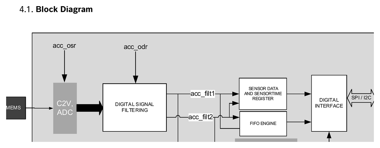
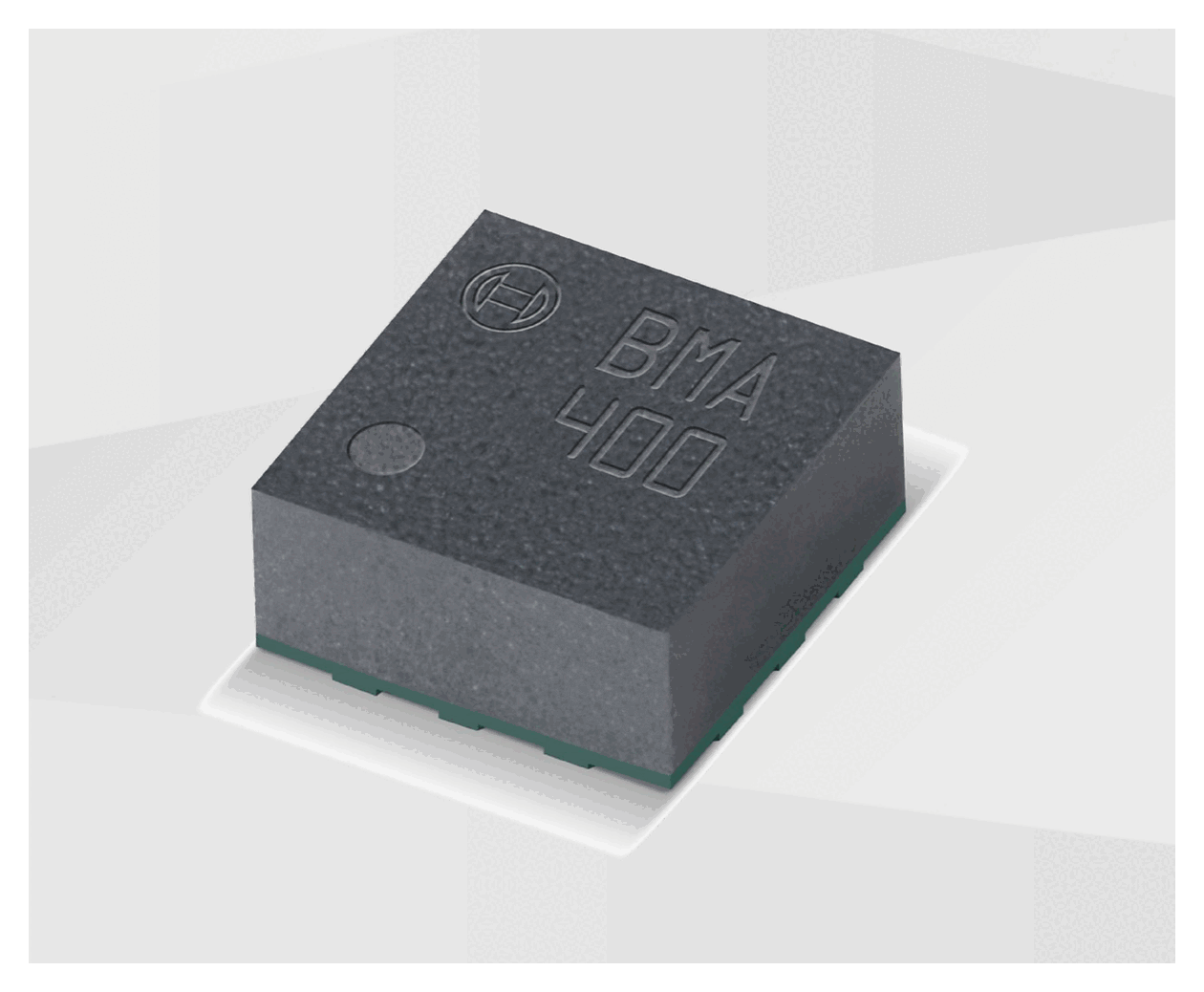
Bosch Sensortec BMA400. 12-bit triaxial accelerometer, ±2g/±4g/±8g/±16g, <14.5µA normal mode. Step counter, activity recognition, tap detection, 1KB FIFO, SPI/I²C. LGA-12 2×2×0.95mm.
Paste this into Claude Code (VS Code panel, Adom editor, or terminal) to install:
Search the Adom Wiki for the datasheet "BMA400 — 3-axis Ultra-Low-Power Accelerometer" (slug: bma400) at https://wiki-ufypy5dpx93o.adom.cloud/wiki/datasheets/bma400. Download the standardized markdown and extracted diagram images into my project's datasheets/bma400/ directory. Show me the key specifications and pin configuration.
Source: Bosch Sensortec BMA400 Data Sheet (BST-BMA400-DS000-14) Manufacturer: Bosch Sensortec Part Number: BMA400 Document: BST-BMA400-DS000-14 — Rev 2.3, July 2025
Description
The BMA400 is a 12-bit, digital, triaxial acceleration sensor with smart on-chip motion and position-triggered interrupt features. It is Bosch Sensortec's first ultra-low-power accelerometer, offering full programmability with an advanced set of integrated motion-detection algorithms while keeping supply current under 14.5 µA at the highest performance mode. A dedicated step counter supports extended battery life in wearables at a current consumption of only 4 µA.
The sensor targets coin-cell-powered IoT products, smartwatches, fitness trackers, and door/window alarm devices, where always-on motion detection is needed without draining the battery.
Key Specifications
Features
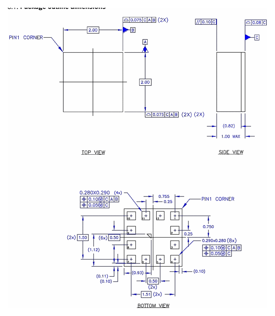
- • Small LGA-12 package, footprint 2 mm × 2 mm, height 0.95 mm
- • Ultra-low-power operation — < 14.5 µA with highest performance
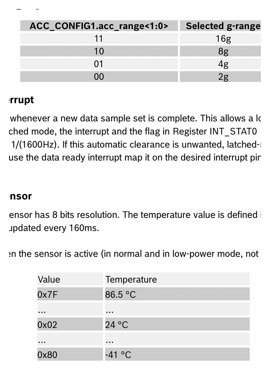
- • Programmable acceleration ranges (±2 g / ±4 g / ±8 g / ±16 g)
- • Low-pass filter bandwidth selectable at 0.48 × ODR
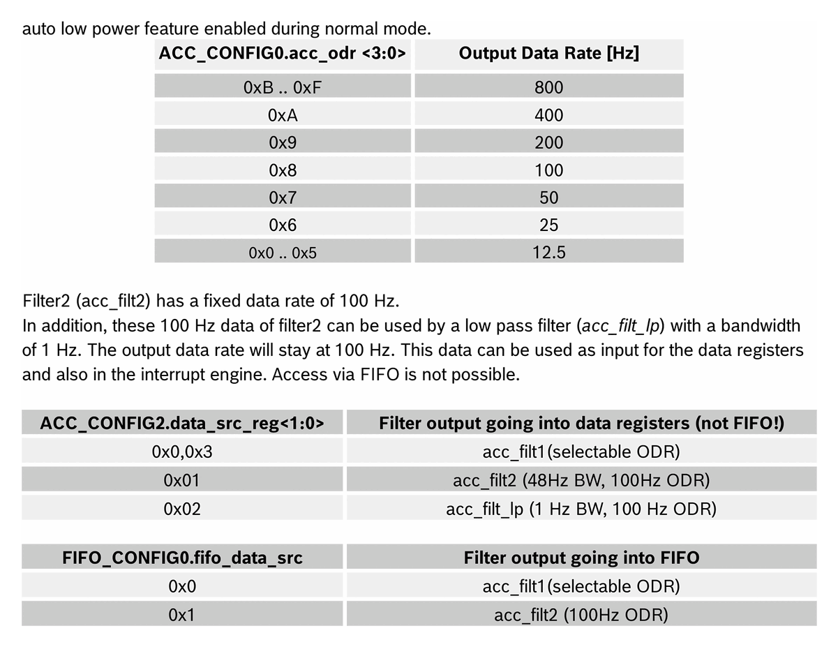
- • Output data rate up to 800 Hz
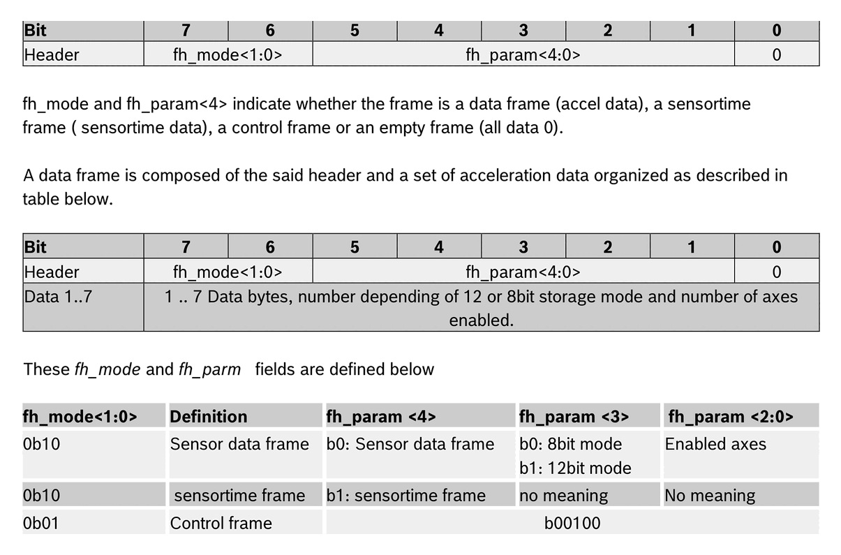
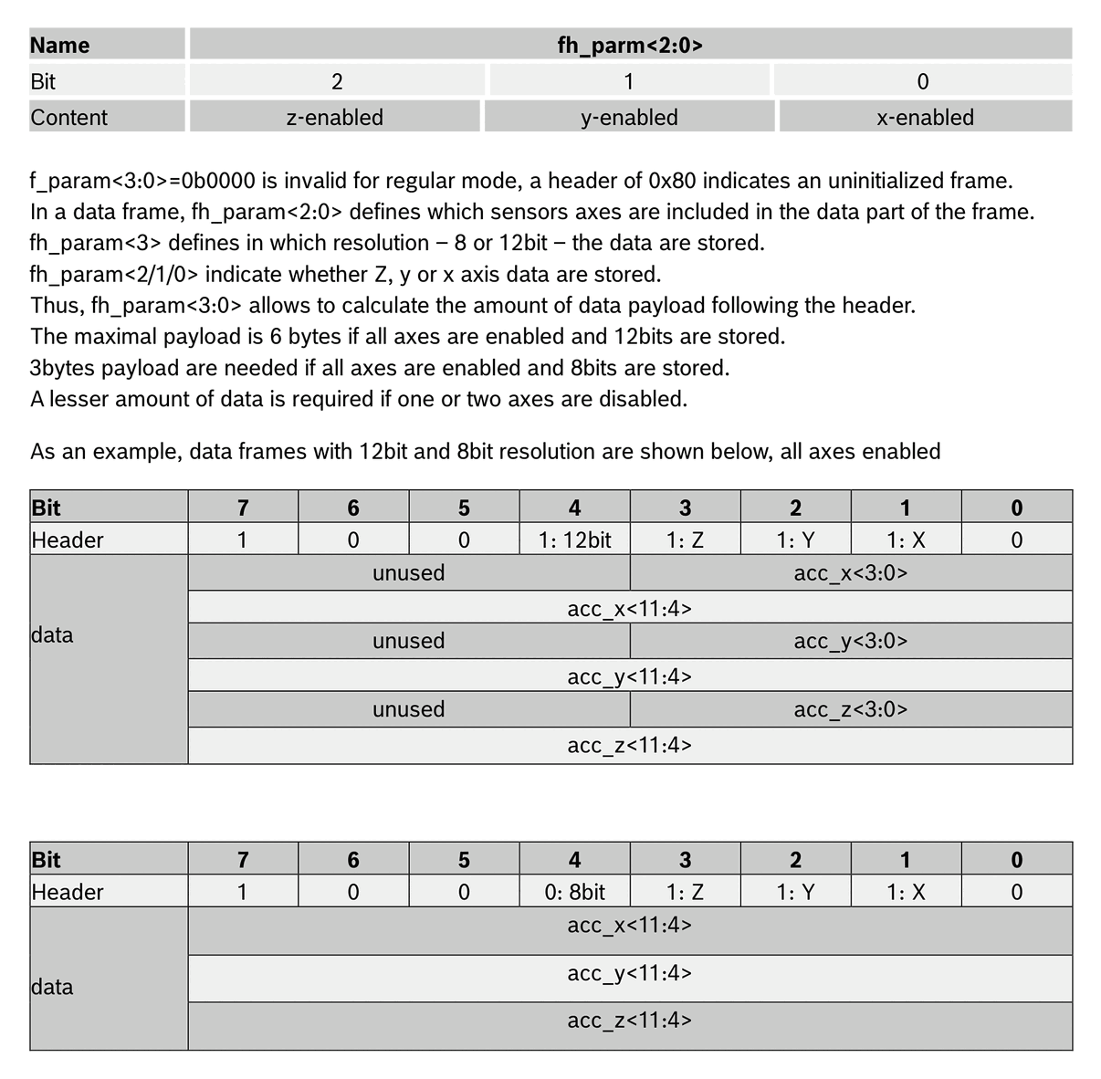
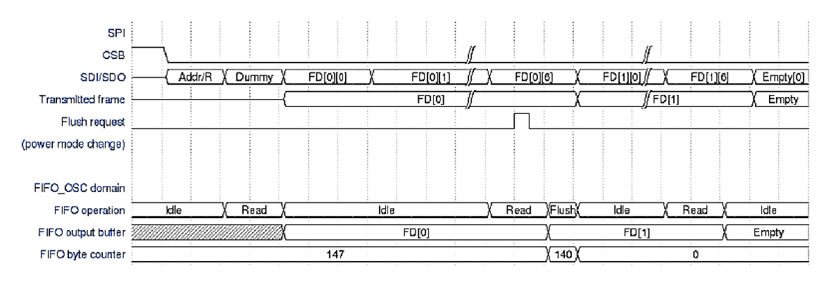
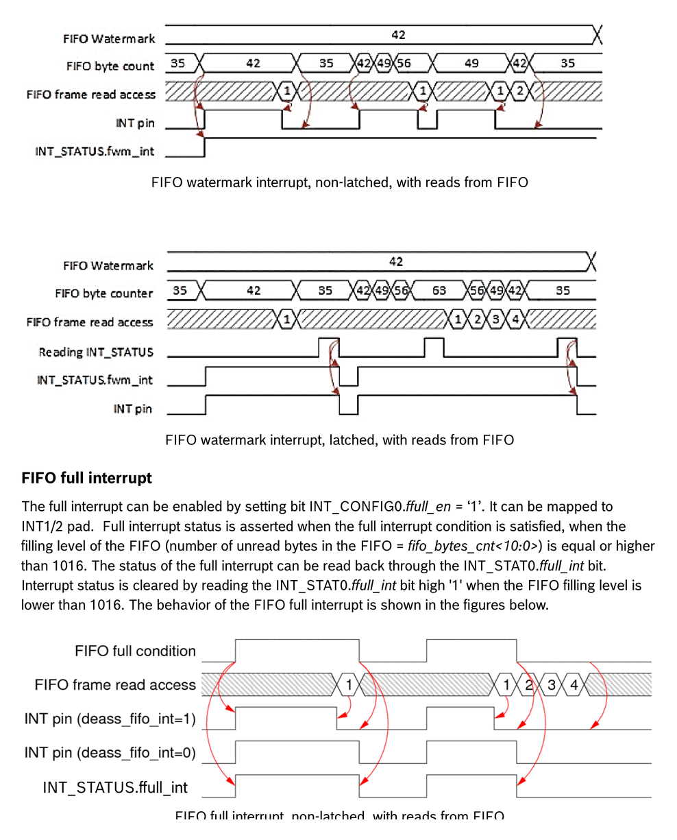
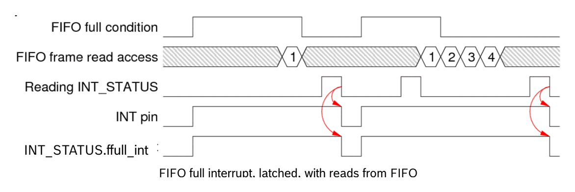
- • Integrated 1 KB FIFO with watermark and full interrupts
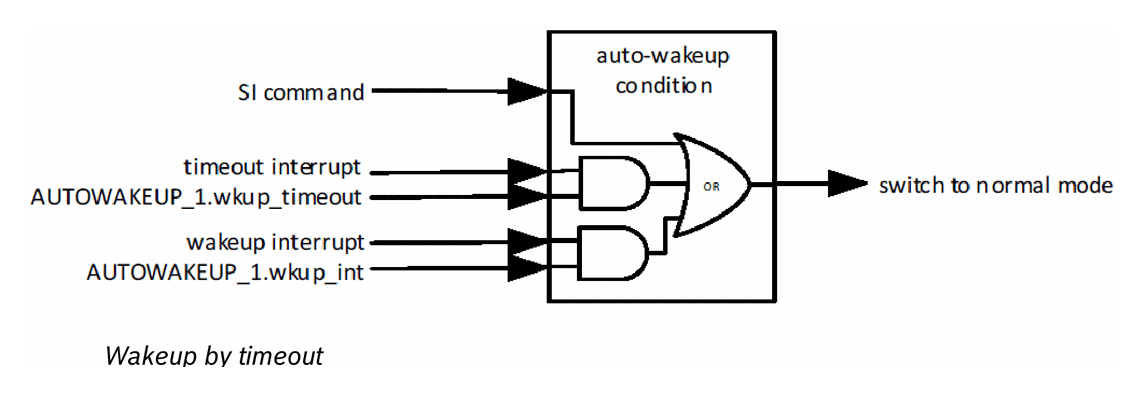
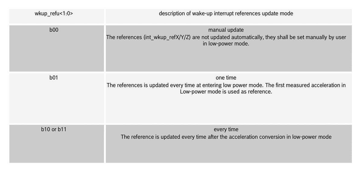
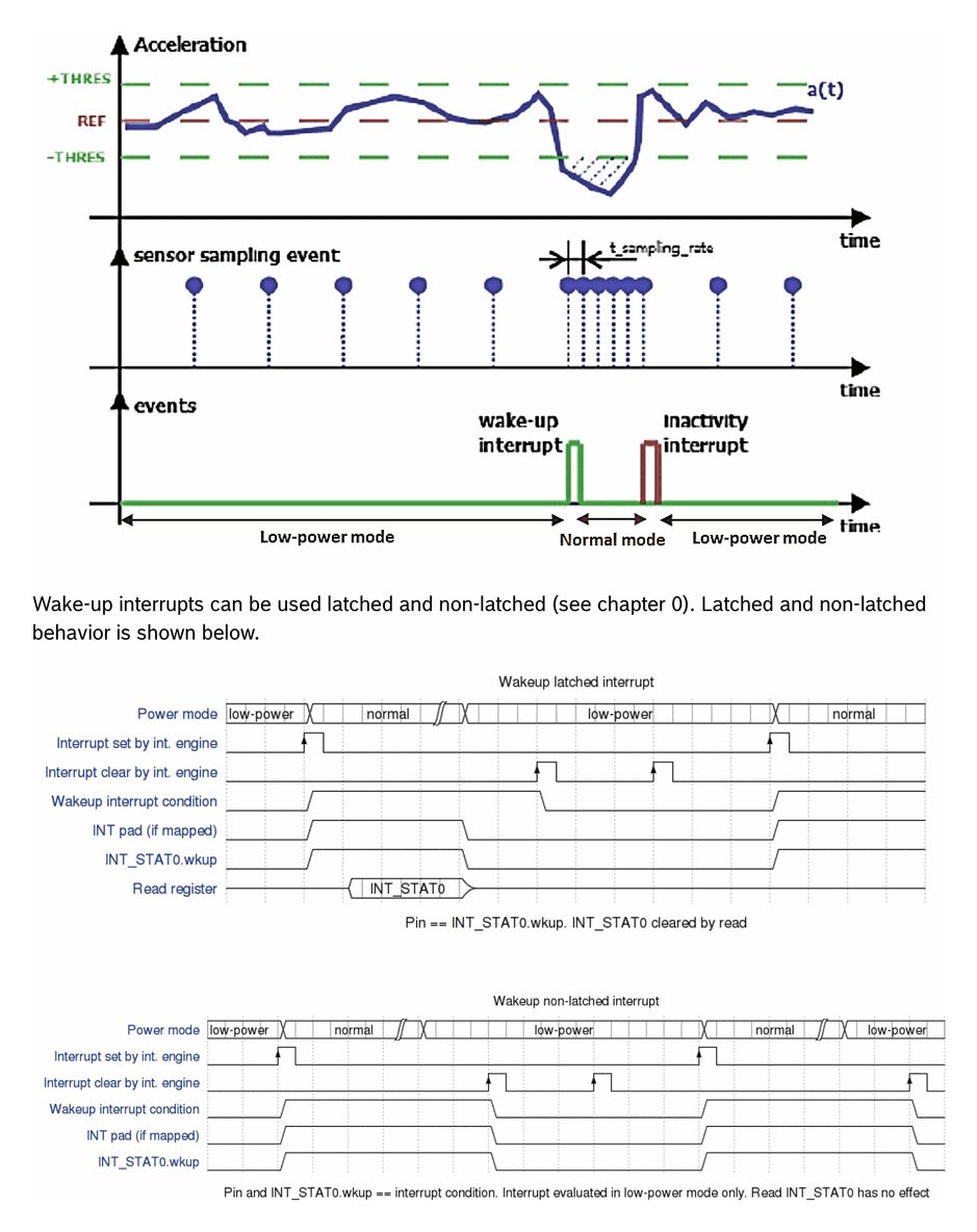
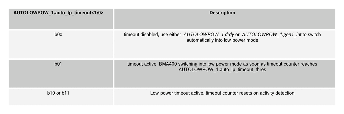
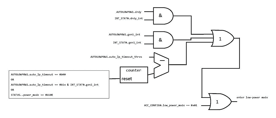
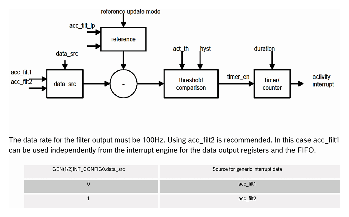
- • On-chip interrupt engine: auto-wakeup, auto-low-power, activity/in-activity
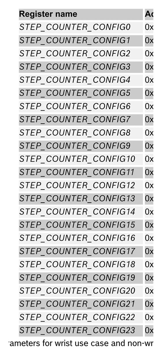
- • Step counter with 4 µA system current consumption
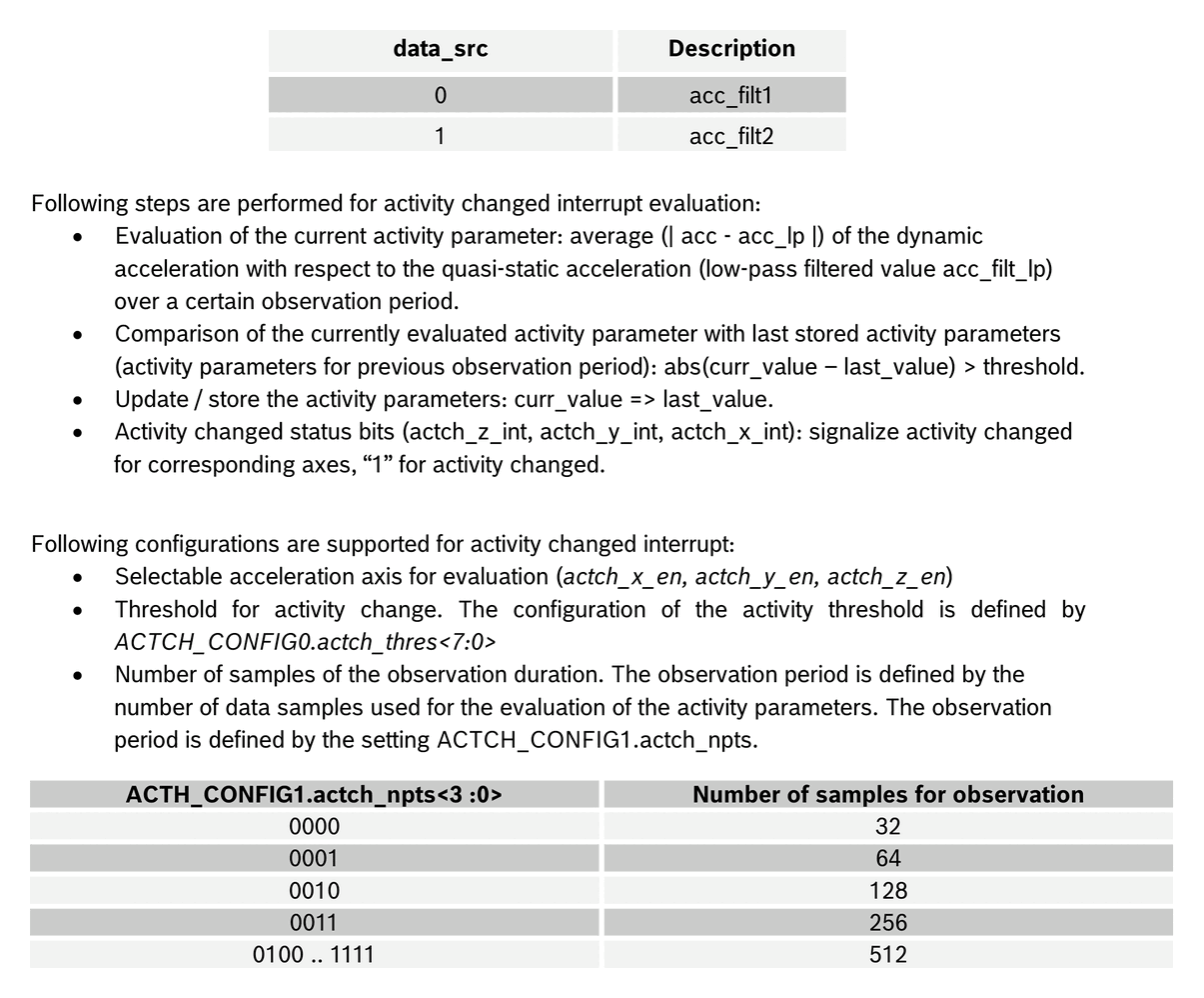
- • Activity recognition (walking, running, standing still)
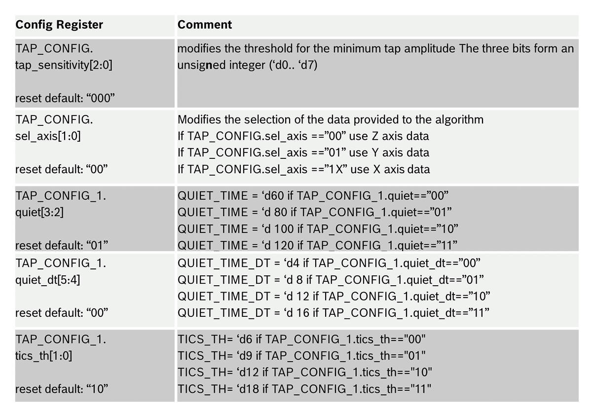
- • Tap / double-tap detection
- • Orientation detection
- • SPI (4-wire, 3-wire), I²C, two interrupt pins
- • V<sub>DDIO</sub> range 1.2 V – 3.6 V
- • RoHS compliant, halogen-free
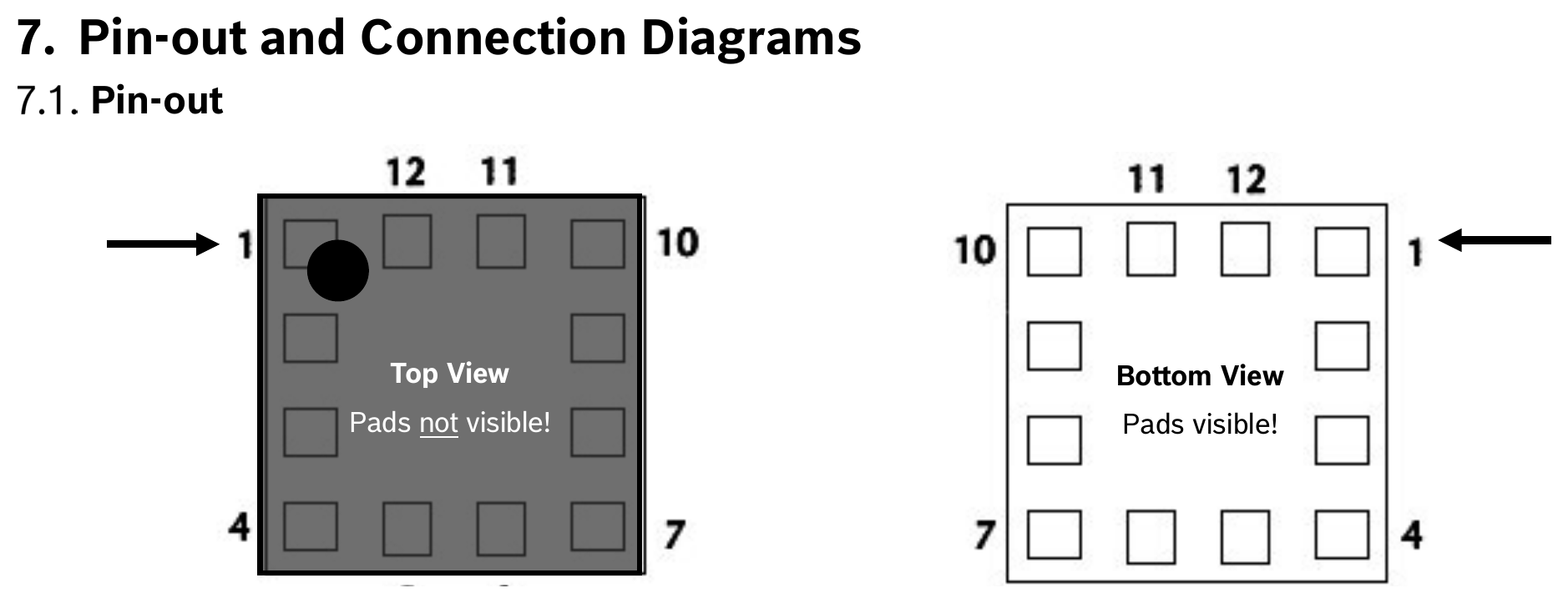
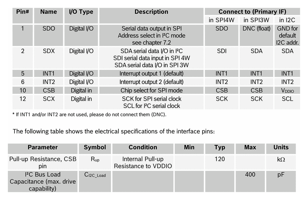
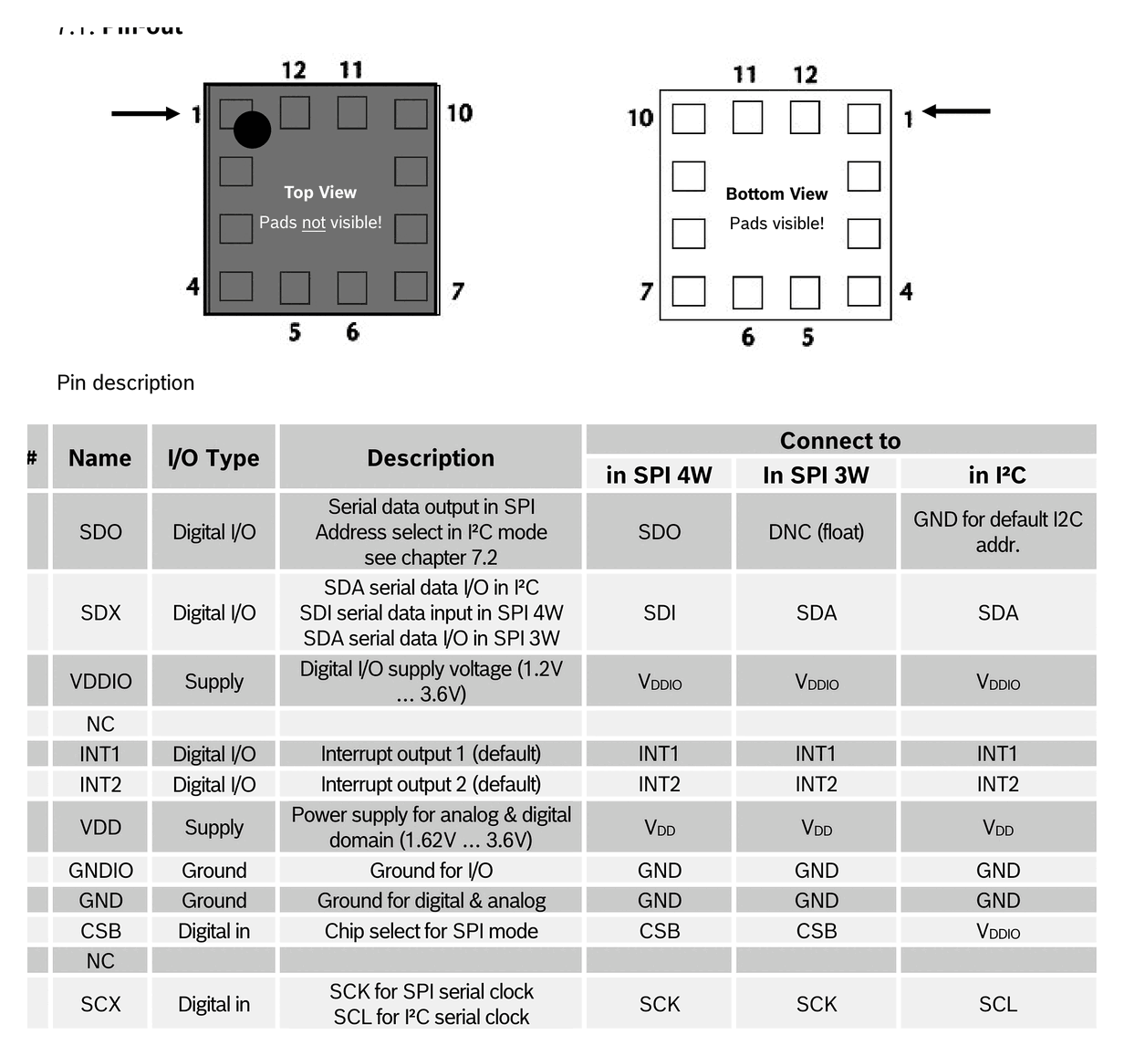
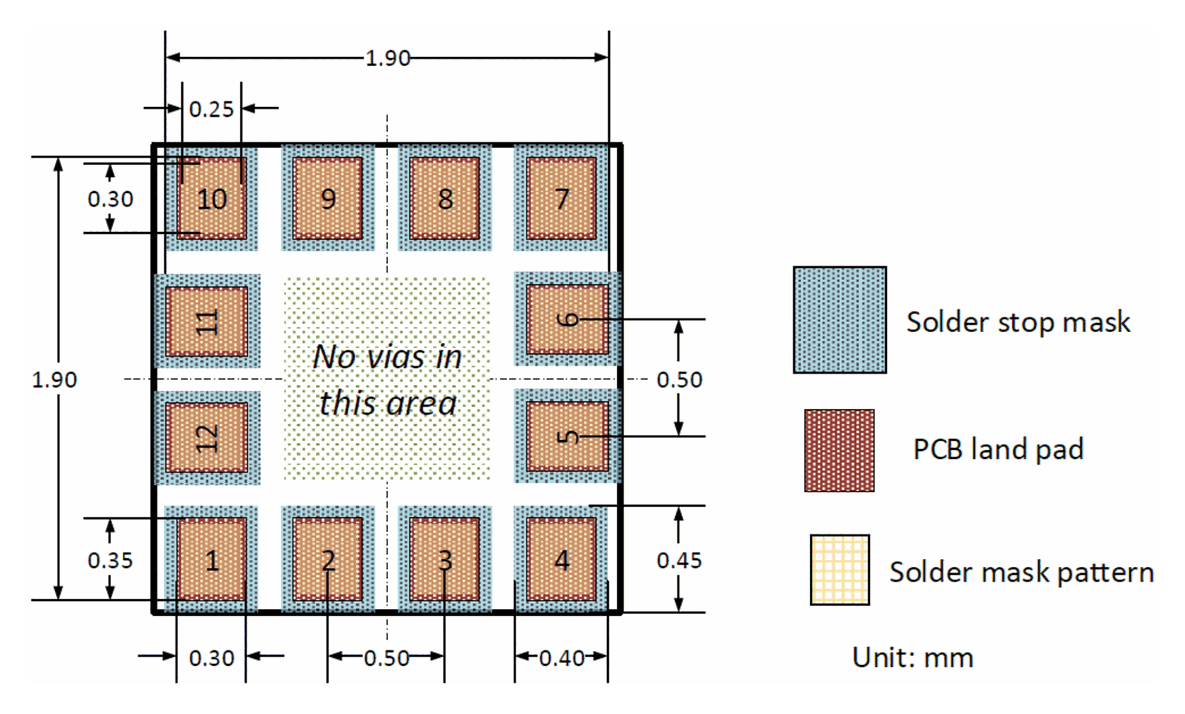
Pin Configuration
Source: Bosch Sensortec BMA400 Data Sheet (BST-BMA400-DS000-14) Manufacturer: Bosch Sensortec Part Number: BMA400 Document: BST-BMA400-DS000-14 — Rev 2.3, July 2025
Absolute Maximum Ratings
| Parameter | Condition | Min | Max | Units |
|---|---|---|---|---|
| Voltage at Supply Pin | V<sub>DD</sub> Pin | −0.3 | 4 | V |
| Voltage at Supply Pin | V<sub>DDIO</sub> Pin | −0.3 | 4 | V |
| Voltage at any Logic Pin | Non-Supply Pin | −0.3 | V<sub>DDIO</sub>+0.3, < 4 | V |
| Passive Storage Temp. Range | ≤ 65 % rel. H. | −50 | +150 | °C |
| Mechanical Shock | Duration ≤ 200 µs | — | 10 000 | g |
| Mechanical Shock | Duration ≤ 1.0 ms | — | 2 000 | g |
| Free fall | onto hard surfaces | — | 1.8 | m |
| ESD | HBM, at any pin | — | 2 | kV |
| ESD | CDM | — | 500 | V |
| ESD | MM | — | 200 | V |
> Note. Stress above these limits may cause damage to the device. Exceeding the specified electrical limits may affect reliability or cause malfunction.
Electrical Characteristics
Output Signal
| Parameter | Symbol | Condition | Min | Typ | Max | Units |
|---|---|---|---|---|---|---|
| Sensitivity | S<sub>2g</sub> | g<sub>FS2g</sub>, T<sub>A</sub>=25 °C | — | 1024 | — | LSB/g |
| Sensitivity | S<sub>4g</sub> | g<sub>FS4g</sub>, T<sub>A</sub>=25 °C | — | 512 | — | LSB/g |
| Sensitivity | S<sub>8g</sub> | g<sub>FS8g</sub>, T<sub>A</sub>=25 °C | — | 256 | — | LSB/g |
| Sensitivity | S<sub>16g</sub> | g<sub>FS16g</sub>, T<sub>A</sub>=25 °C | — | 128 | — | LSB/g |
| Sensitivity Temp. Drift | TCS | Nominal V<sub>DD</sub>/V<sub>DDIO</sub>, g<sub>FS4g</sub> | — | 0.025 | — | %/K |
| Zero-g Offset | Off | Nominal V<sub>DD</sub>/V<sub>DDIO</sub>, g<sub>FS4g</sub> | — | 50 | — | mg |
| Zero-g Offset Temp. Drift | TCO | Nominal V<sub>DD</sub>/V<sub>DDIO</sub>, g<sub>FS4g</sub> | — | 1 | — | mg/K |
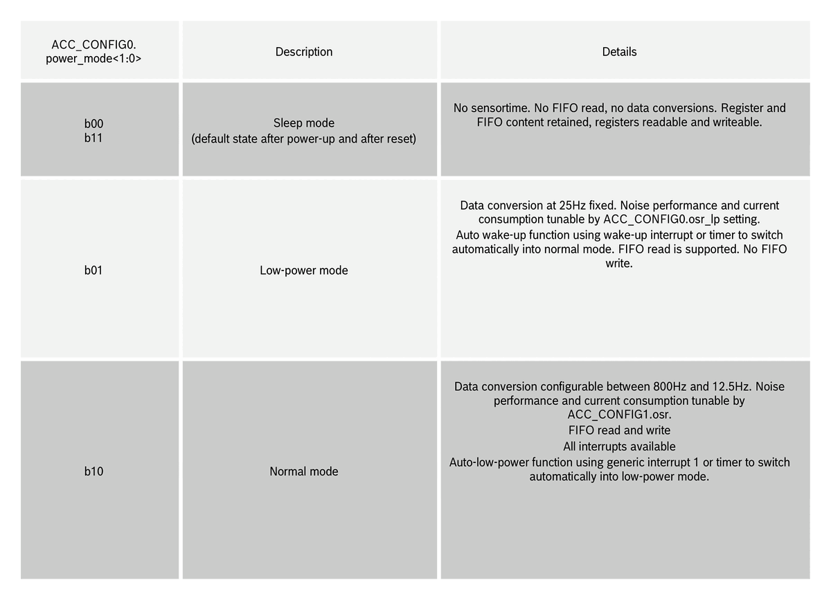
| Output Data Rate | ODR<sub>NORM</sub> | Normal mode | 12.5 | — | 800 | Hz |
| Output Data Rate | ODR<sub>LPM</sub> | Low-power mode | — | 25 | — | Hz |
| Bandwidth | BW<sub>NORM</sub> | 3 dB cutoff selectable in normal mode | 0.24 × ODR<sub>NORM</sub> | — | 0.48 × ODR<sub>NORM</sub> | Hz |
| Nonlinearity | NL | Nominal V<sub>DD</sub>/V<sub>DDIO</sub> | — | 0.5 | — | %FS |
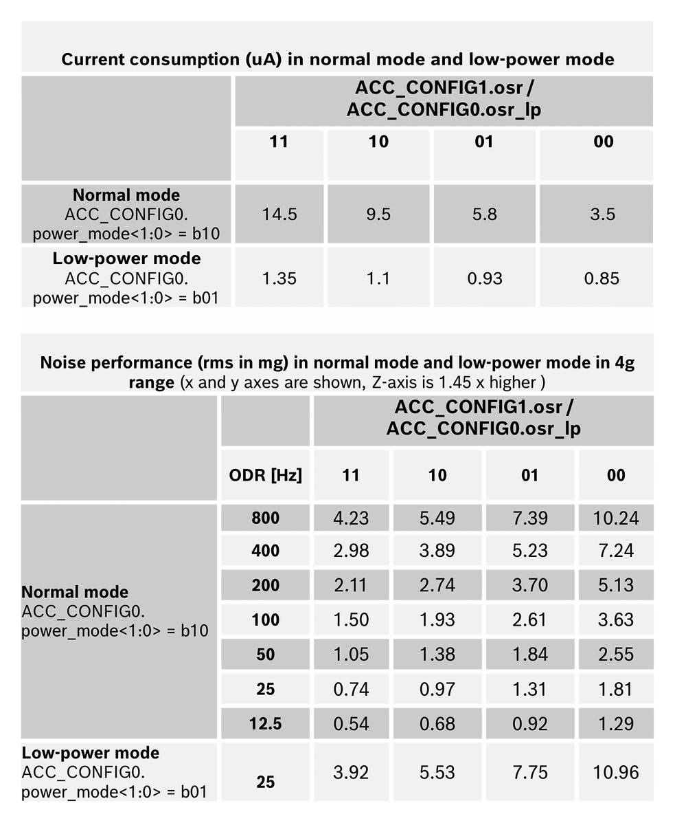
| Output Noise Density | n<sub>RMS</sub> | Nominal V<sub>DD</sub>/V<sub>DDIO</sub>, OSR<3, X/Y-axis | — | 180 | — | µg/√Hz |
| Output Noise Density | n<sub>RMS</sub> | Nominal V<sub>DD</sub>/V<sub>DDIO</sub>, OSR<3, Z-axis | — | 240 | — | µg/√Hz |
Mechanical Characteristics
| Parameter | Symbol | Condition | Typ | Units |
|---|---|---|---|---|
| Cross-Axis Sensitivity | S | relative contribution between any two axes | 2 | % |
| Alignment Error | E<sub>A</sub> | relative to package outline | 0.5 | ° |
Current Consumption
| Parameter | Symbol | Condition | Typ | Units |
|---|---|---|---|---|
| Supply Current — Normal mode | I<sub>DD</sub> | V<sub>DD</sub>=1.8 V, OSR=3 | 14.5 | µA |
| Supply Current — Normal mode | I<sub>DD</sub> | OSR=0 | 3.5 | µA |
| Supply Current — Sleep mode | I<sub>DDsleep</sub> | V<sub>DD</sub>=1.8 V, 25 °C | 160 | nA |
| Supply Current — Low-power mode | I<sub>DDlpf</sub> | V<sub>DD</sub>=1.8 V, 25 Hz ODR, OSR=0 | 850 | nA |
| Wake-up Time | t<sub>w_up</sub> | From sleep to normal mode | 2 / ODR | ms |
| Power-Up Time | t<sub>s_up</sub> | From device start | 1 | ms |
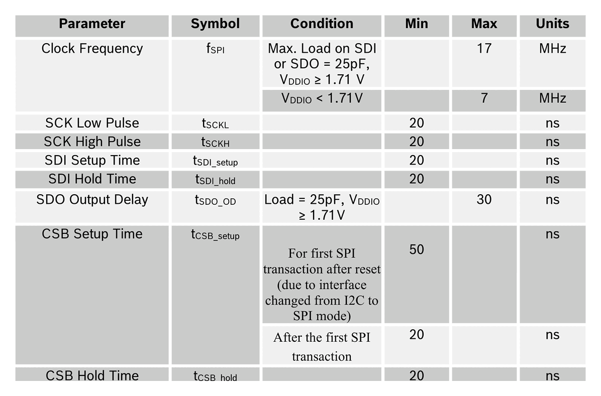
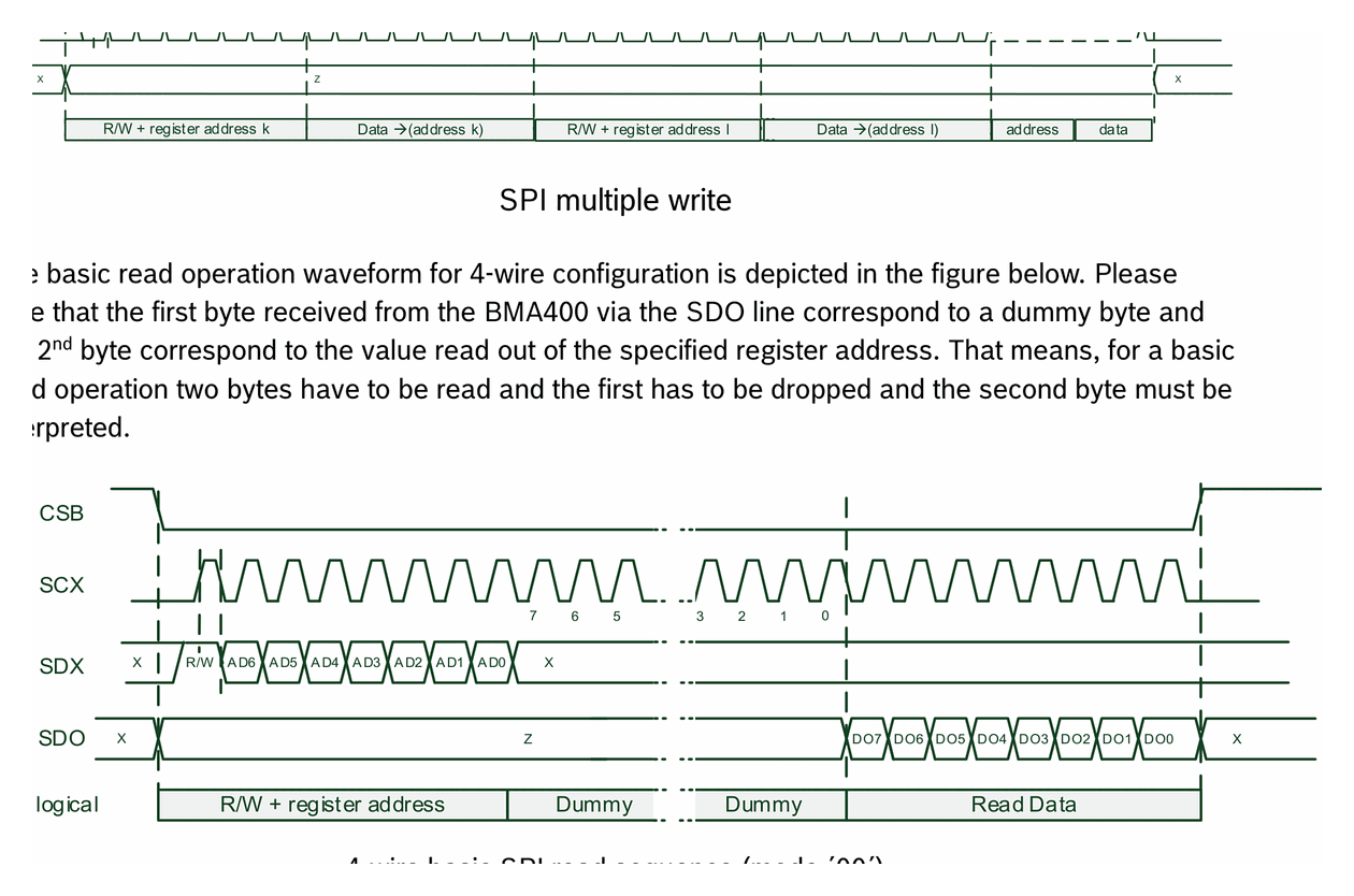
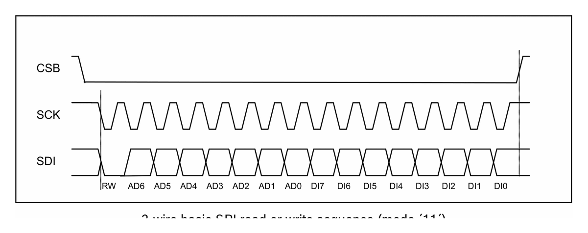
Communication Interface
| Parameter | Default | Configurable |
|---|---|---|
| Primary interface | I²C | Yes, SPI via register |
| SPI modes | 4-wire | 4-wire / 3-wire |
| I²C speed | Fast-mode 400 kHz | Standard / Fast / Fast+ |
| SPI clock | up to 10 MHz | — |
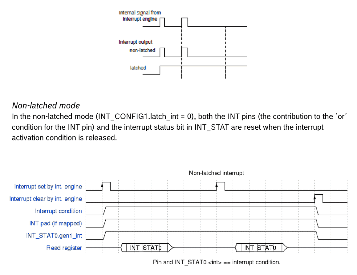
| Interrupt pins | 2 (INT1, INT2) | Mapping configurable |
Applications
- Step counting for extended-battery-life wearables
- Always-on motion detection in IoT devices and smart watches
- Advanced system-level power management for mobile devices
- Fitness and activity-tracking applications
- Tap / double-tap input detection
- Drop detection for warranty / transport logging
- Window/door state sensing for climate-control and alarm systems
- Battery-powered products operating from coin cells requiring < 1 µA average and auto-wakeup functionality
Diagrams & Graphs (53)
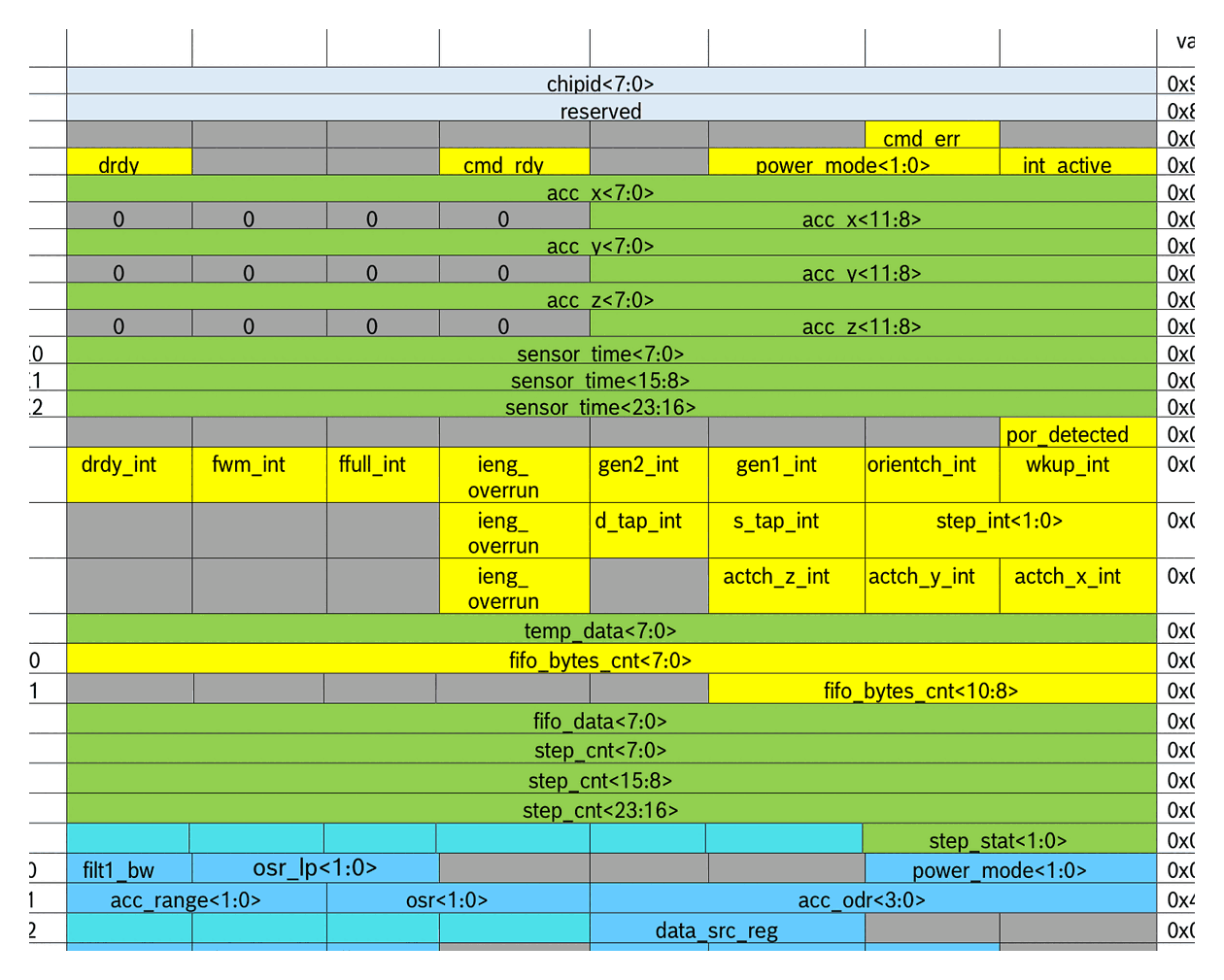
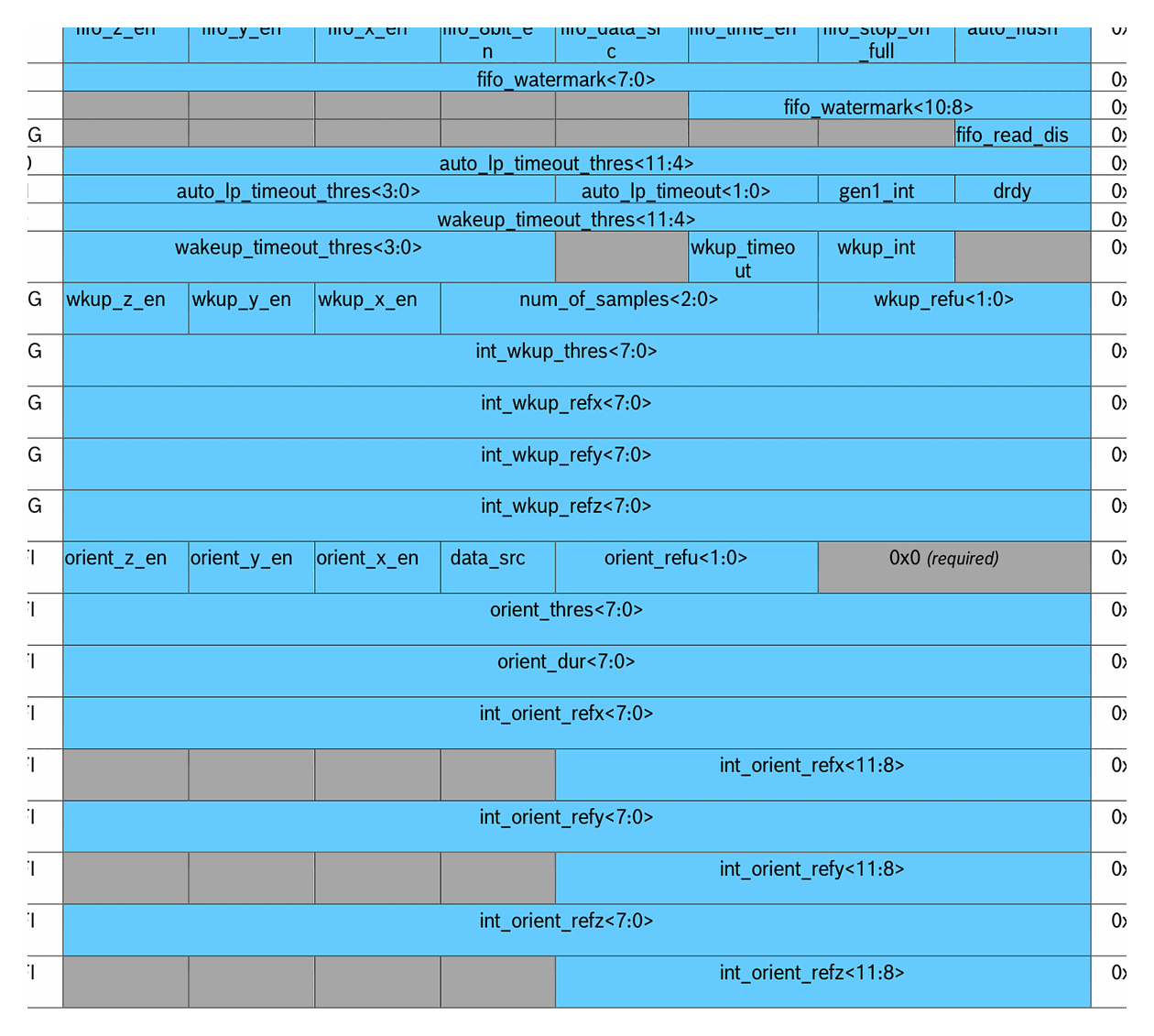
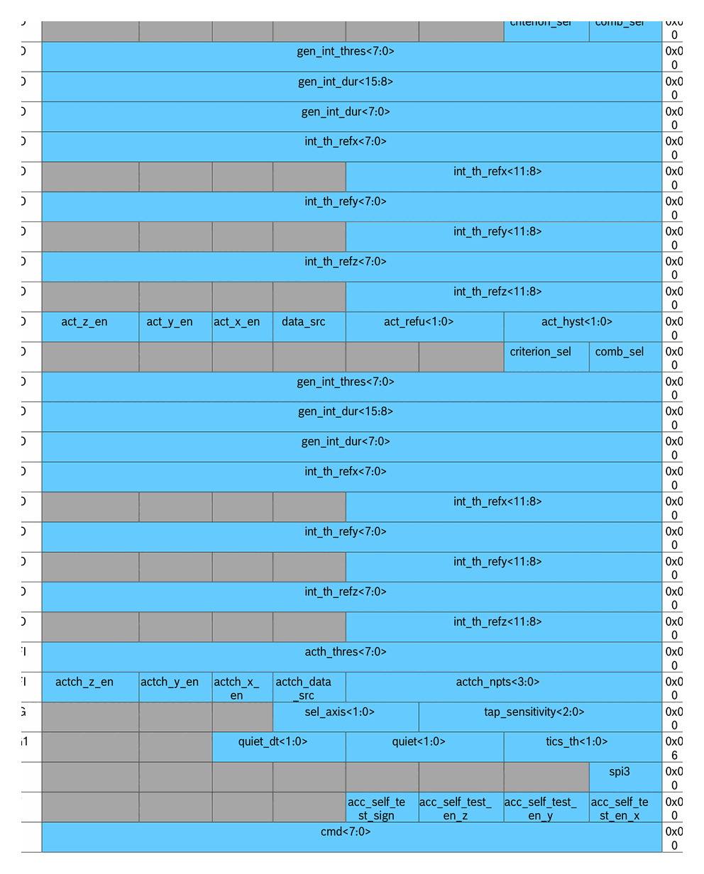
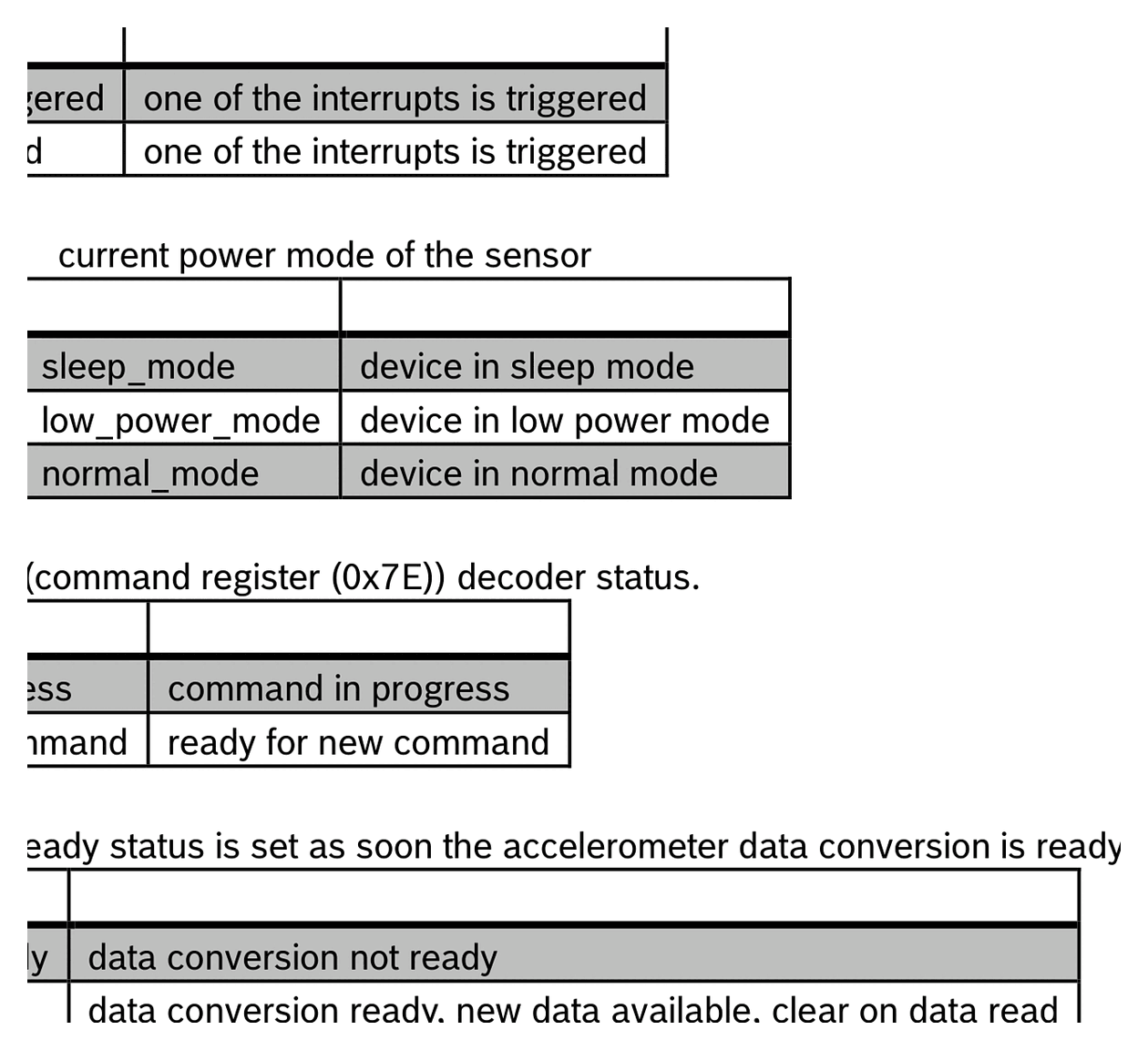
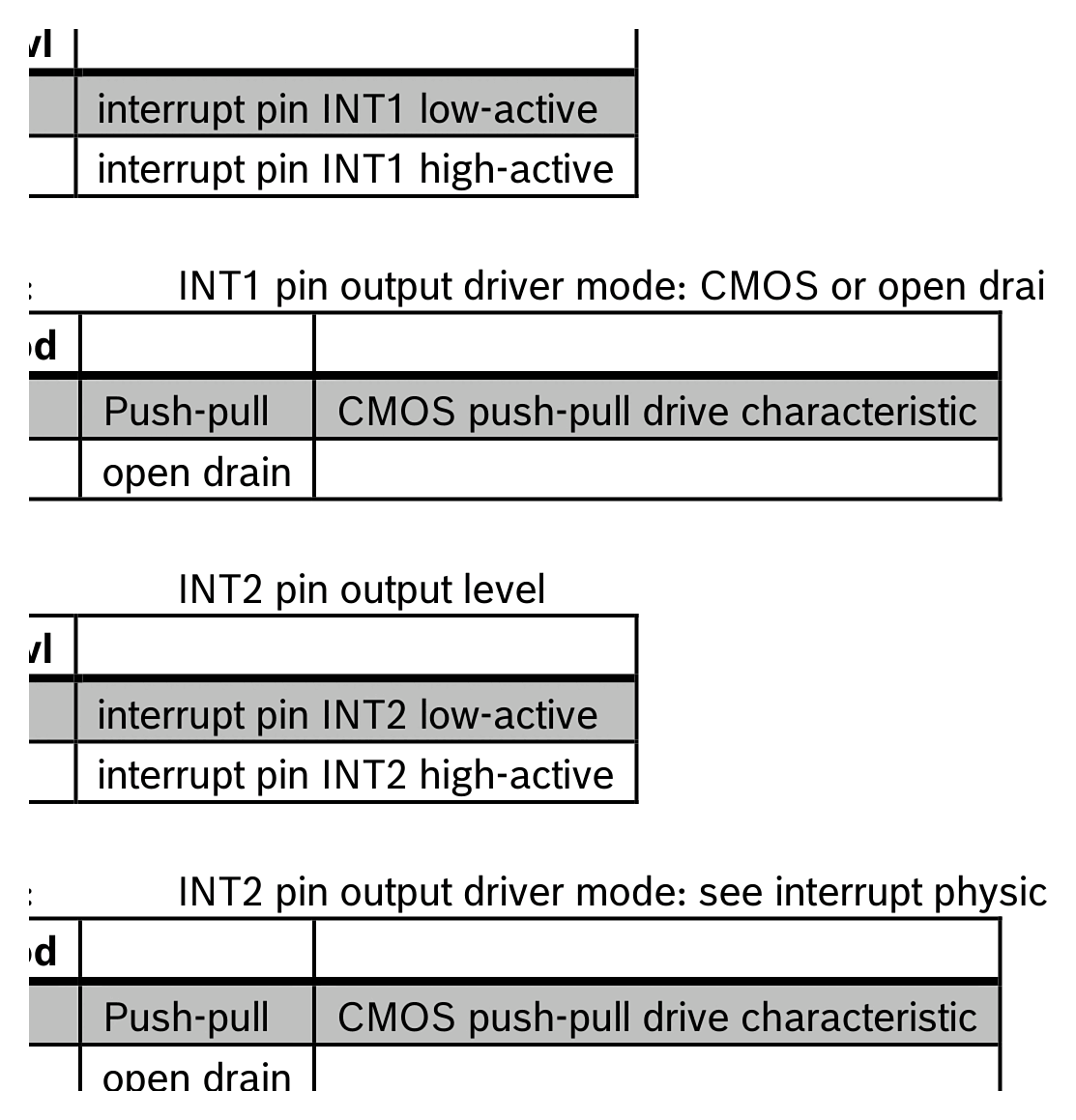
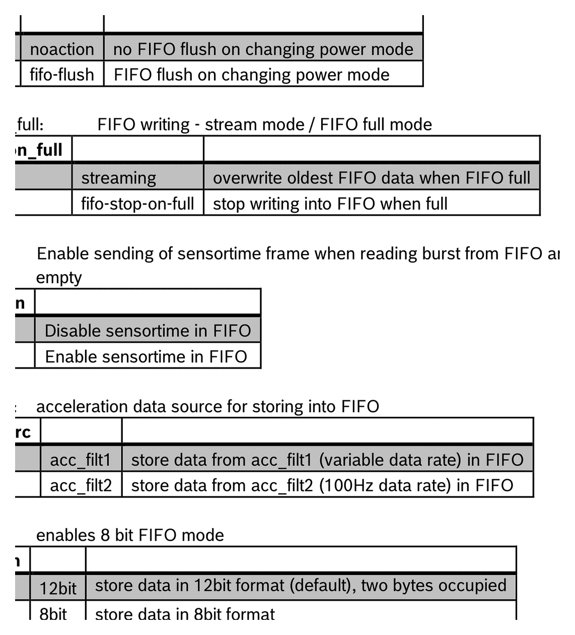
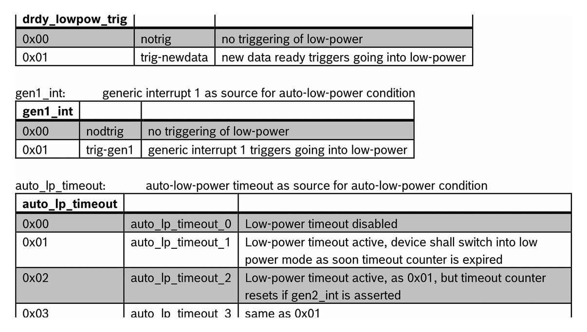
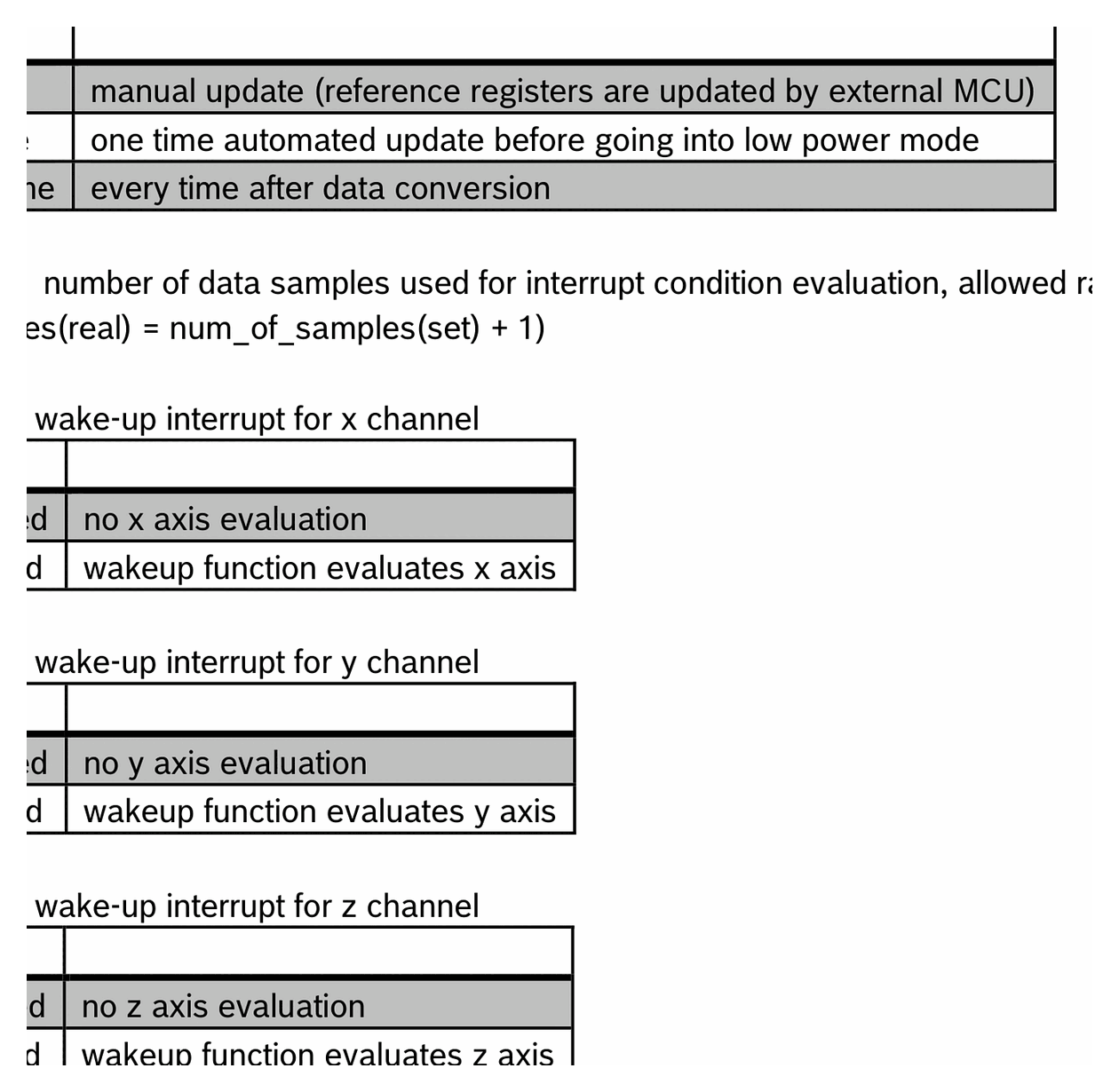
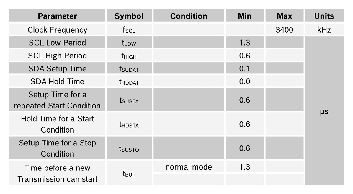
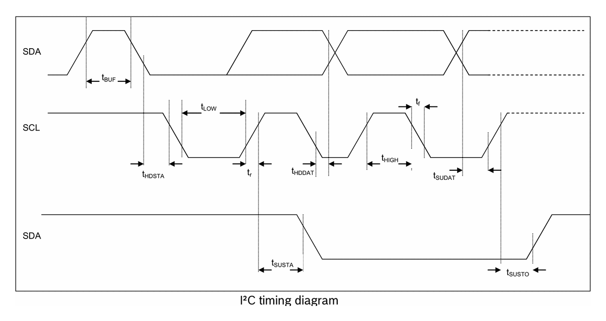
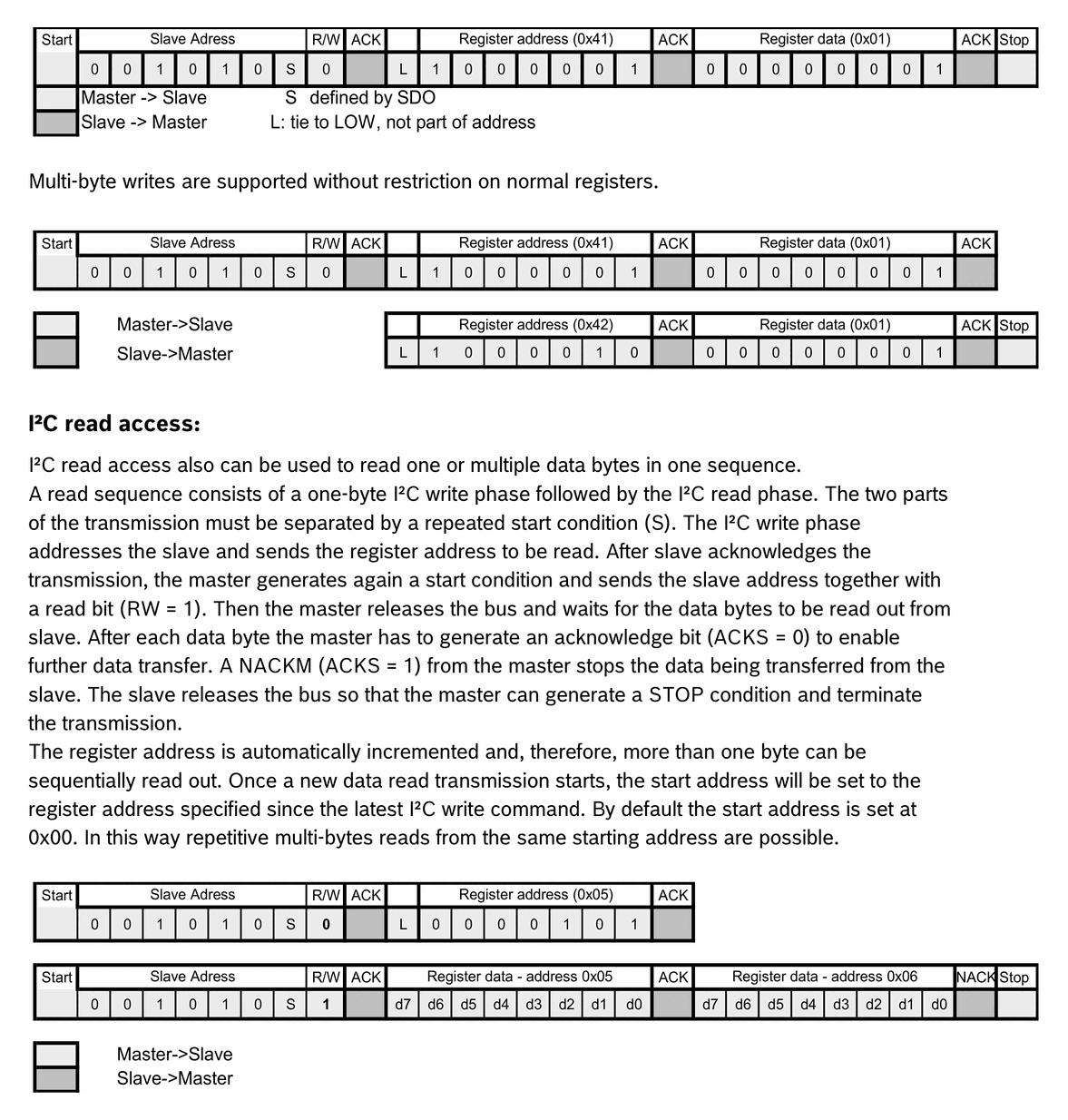
**Source:** [Bosch Sensortec BMA400 Data Sheet (BST-BMA400-DS000-14)](https://www.bosch-sensortec.com/media/boschsensortec/downloads/datasheets/bst-bma400-ds000.pdf)
**Manufacturer:** Bosch Sensortec
**Part Number:** BMA400
**Document:** BST-BMA400-DS000-14 — Rev 2.3, July 2025

## Description

The BMA400 is a 12-bit, digital, triaxial acceleration sensor with smart on-chip motion and position-triggered interrupt features. It is Bosch Sensortec's first ultra-low-power accelerometer, offering full programmability with an advanced set of integrated motion-detection algorithms while keeping supply current under 14.5 µA at the highest performance mode. A dedicated step counter supports extended battery life in wearables at a current consumption of only 4 µA.

The sensor targets coin-cell-powered IoT products, smartwatches, fitness trackers, and door/window alarm devices, where always-on motion detection is needed without draining the battery.

## Key Specifications

| Parameter | Value |
| --- | --- |
| Resolution | 12 bit |
| Acceleration Ranges | ±2g / ±4g / ±8g / ±16g |
| Output Data Rate | 12.5 Hz – 800 Hz |
| Current (normal mode) | < 14.5 µA |
| Current (step counter only) | 4 µA |
| Current (sleep mode) | 160 nA |
| Current (low-power mode, 25 Hz ODR) | 850 nA |
| Supply Voltage V<sub>DD</sub> | 1.72 – 3.6 V |
| Supply Voltage V<sub>DDIO</sub> | 1.2 – 3.6 V |
| Operating Temperature | −40 °C to +85 °C |
| Package | LGA-12, 2.0 × 2.0 × 0.95 mm |
| FIFO Depth | 1024 bytes |
| Digital Interface | I²C, SPI (4-wire and 3-wire) |
| Interrupt Pins | 2 |

## Features

- Small LGA-12 package, footprint 2 mm × 2 mm, height 0.95 mm
- Ultra-low-power operation — < 14.5 µA with highest performance
- Programmable acceleration ranges (±2 g / ±4 g / ±8 g / ±16 g)
- Low-pass filter bandwidth selectable at 0.48 × ODR
- Output data rate up to 800 Hz
- Integrated 1 KB FIFO with watermark and full interrupts
- On-chip interrupt engine: auto-wakeup, auto-low-power, activity/in-activity
- Step counter with 4 µA system current consumption
- Activity recognition (walking, running, standing still)
- Tap / double-tap detection
- Orientation detection
- SPI (4-wire, 3-wire), I²C, two interrupt pins
- V<sub>DDIO</sub> range 1.2 V – 3.6 V
- RoHS compliant, halogen-free

## Pin Configuration

| Pin | Name | Type | Description |
| --- | --- | --- | --- |
| 1 | SDO | Digital I/O | Serial data output in SPI mode; I²C address-select in I²C mode |
| 2 | SDX | Digital I/O | SDA in I²C; SDI in 4-wire SPI; SDA in 3-wire SPI |
| 3 | VDDIO | Supply | Digital I/O supply voltage (1.2 – 3.6 V) |
| 4 | NC | — | Not connected |
| 5 | INT1 | Digital I/O | Interrupt output 1 (default) |
| 6 | INT2 | Digital I/O | Interrupt output 2 (default) |
| 7 | VDD | Supply | Analog and digital supply (1.62 – 3.6 V) |
| 8 | GNDIO | Ground | Ground for digital I/O domain |
| 9 | GND | Ground | Analog and digital ground |
| 10 | CSB | Digital In | Chip-select for SPI mode |
| 11 | NC | — | Not connected |
| 12 | SCX | Digital In | SCK in SPI mode; SCL in I²C mode |

## Absolute Maximum Ratings

| Parameter | Condition | Min | Max | Units |
| --- | --- | --- | --- | --- |
| Voltage at Supply Pin | V<sub>DD</sub> Pin | −0.3 | 4 | V |
| Voltage at Supply Pin | V<sub>DDIO</sub> Pin | −0.3 | 4 | V |
| Voltage at any Logic Pin | Non-Supply Pin | −0.3 | V<sub>DDIO</sub>+0.3, < 4 | V |
| Passive Storage Temp. Range | ≤ 65 % rel. H. | −50 | +150 | °C |
| Mechanical Shock | Duration ≤ 200 µs | — | 10 000 | g |
| Mechanical Shock | Duration ≤ 1.0 ms | — | 2 000 | g |
| Free fall | onto hard surfaces | — | 1.8 | m |
| ESD | HBM, at any pin | — | 2 | kV |
| ESD | CDM | — | 500 | V |
| ESD | MM | — | 200 | V |

> **Note.** Stress above these limits may cause damage to the device. Exceeding the specified electrical limits may affect reliability or cause malfunction.

## Electrical Characteristics

### Output Signal

| Parameter | Symbol | Condition | Min | Typ | Max | Units |
| --- | --- | --- | --- | --- | --- | --- |
| Sensitivity | S<sub>2g</sub> | g<sub>FS2g</sub>, T<sub>A</sub>=25 °C | — | 1024 | — | LSB/g |
| Sensitivity | S<sub>4g</sub> | g<sub>FS4g</sub>, T<sub>A</sub>=25 °C | — | 512 | — | LSB/g |
| Sensitivity | S<sub>8g</sub> | g<sub>FS8g</sub>, T<sub>A</sub>=25 °C | — | 256 | — | LSB/g |
| Sensitivity | S<sub>16g</sub> | g<sub>FS16g</sub>, T<sub>A</sub>=25 °C | — | 128 | — | LSB/g |
| Sensitivity Temp. Drift | TCS | Nominal V<sub>DD</sub>/V<sub>DDIO</sub>, g<sub>FS4g</sub> | — | 0.025 | — | %/K |
| Zero-g Offset | Off | Nominal V<sub>DD</sub>/V<sub>DDIO</sub>, g<sub>FS4g</sub> | — | 50 | — | mg |
| Zero-g Offset Temp. Drift | TCO | Nominal V<sub>DD</sub>/V<sub>DDIO</sub>, g<sub>FS4g</sub> | — | 1 | — | mg/K |
| Output Data Rate | ODR<sub>NORM</sub> | Normal mode | 12.5 | — | 800 | Hz |
| Output Data Rate | ODR<sub>LPM</sub> | Low-power mode | — | 25 | — | Hz |
| Bandwidth | BW<sub>NORM</sub> | 3 dB cutoff selectable in normal mode | 0.24 × ODR<sub>NORM</sub> | — | 0.48 × ODR<sub>NORM</sub> | Hz |
| Nonlinearity | NL | Nominal V<sub>DD</sub>/V<sub>DDIO</sub> | — | 0.5 | — | %FS |
| Output Noise Density | n<sub>RMS</sub> | Nominal V<sub>DD</sub>/V<sub>DDIO</sub>, OSR<3, X/Y-axis | — | 180 | — | µg/√Hz |
| Output Noise Density | n<sub>RMS</sub> | Nominal V<sub>DD</sub>/V<sub>DDIO</sub>, OSR<3, Z-axis | — | 240 | — | µg/√Hz |

### Mechanical Characteristics

| Parameter | Symbol | Condition | Typ | Units |
| --- | --- | --- | --- | --- |
| Cross-Axis Sensitivity | S | relative contribution between any two axes | 2 | % |
| Alignment Error | E<sub>A</sub> | relative to package outline | 0.5 | ° |

### Current Consumption

| Parameter | Symbol | Condition | Typ | Units |
| --- | --- | --- | --- | --- |
| Supply Current — Normal mode | I<sub>DD</sub> | V<sub>DD</sub>=1.8 V, OSR=3 | 14.5 | µA |
| Supply Current — Normal mode | I<sub>DD</sub> | OSR=0 | 3.5 | µA |
| Supply Current — Sleep mode | I<sub>DDsleep</sub> | V<sub>DD</sub>=1.8 V, 25 °C | 160 | nA |
| Supply Current — Low-power mode | I<sub>DDlpf</sub> | V<sub>DD</sub>=1.8 V, 25 Hz ODR, OSR=0 | 850 | nA |
| Wake-up Time | t<sub>w_up</sub> | From sleep to normal mode | 2 / ODR | ms |
| Power-Up Time | t<sub>s_up</sub> | From device start | 1 | ms |

## Communication Interface

| Parameter | Default | Configurable |
| --- | --- | --- |
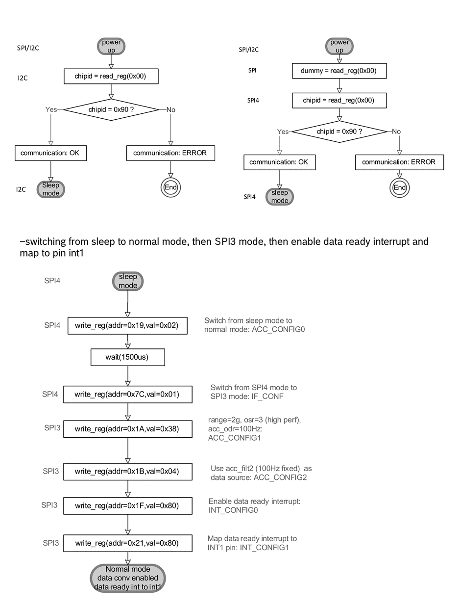
| Primary interface | I²C | Yes, SPI via register |
| SPI modes | 4-wire | 4-wire / 3-wire |
| I²C speed | Fast-mode 400 kHz | Standard / Fast / Fast+ |
| SPI clock | up to 10 MHz | — |
| Interrupt pins | 2 (INT1, INT2) | Mapping configurable |

## Applications

- Step counting for extended-battery-life wearables
- Always-on motion detection in IoT devices and smart watches
- Advanced system-level power management for mobile devices
- Fitness and activity-tracking applications
- Tap / double-tap input detection
- Drop detection for warranty / transport logging
- Window/door state sensing for climate-control and alarm systems
- Battery-powered products operating from coin cells requiring < 1 µA average and auto-wakeup functionality
Sub-Skills
What are Sub-Skills?
Sub-skills are community-contributed AI skill extensions for this component.
They teach AI assistants about specific tools, configurators, or workflows.
Examples:
- A manufacturer’s configuration tool for a motor controller
- A community-written design guide for an amplifier circuit
- An automated test/validation script for a sensor module
How to add one: Click Add Sub-Skill, provide the URL
to your skill and a brief description. Submissions are reviewed by the Adom team
before going live.
Sub-skills are community-contributed AI skill extensions for this component. They teach AI assistants about specific tools, configurators, or workflows.
Examples:
- A manufacturer’s configuration tool for a motor controller
- A community-written design guide for an amplifier circuit
- An automated test/validation script for a sensor module
How to add one: Click Add Sub-Skill, provide the URL to your skill and a brief description. Submissions are reviewed by the Adom team before going live.
No sub-skills yet. Be the first to contribute one!