AP2114H — 1 A Low-Noise CMOS LDO Regulator with Enable
Diodes AP2114. 1 A CMOS LDO with enable, ±1.5 % accuracy, 450 mV dropout @ 1 A, 30 µVrms noise, 60 µA Iq. 1.2/1.5/1.8/2.5/3.3 V fixed + adjustable. SOT-223 through PSOP-8.
Paste this into Claude Code (VS Code panel, Adom editor, or terminal) to install:
Search the Adom Wiki for the datasheet "AP2114H — 1 A Low-Noise CMOS LDO Regulator with Enable" (slug: ap2114h) at https://wiki-ufypy5dpx93o.adom.cloud/wiki/datasheets/ap2114h. Download the standardized markdown and extracted diagram images into my project's datasheets/ap2114h/ directory. Show me the key specifications and pin configuration.
Source: BCD Semiconductor / Diodes Incorporated AP2114 Datasheet Manufacturer: Diodes Incorporated (BCD Semiconductor) Part Number: AP2114 Document: Rev 2.2, January 2013 (1 A Low Noise CMOS LDO Regulator with Enable)
Description
The AP2114 is a CMOS process low-dropout linear regulator with enable function. The regulator delivers a guaranteed 1 A (min) continuous load current. The AP2114 is available in 1.2 V, 1.5 V, 1.8 V, 2.5 V and 3.3 V regulator output and 0.8 V to 5 V adjustable output. It features excellent output accuracy of ±1.5 %, and it is also available in an excellent load regulation and line regulation performance.
The AP2114 features low power consumption.
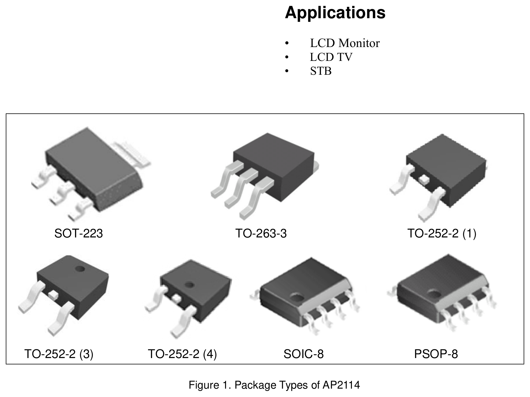
Packages: SOT-223, TO-252-2(1) / (3) / (4), TO-263-3, SOIC-8, PSOP-8.
Key Specifications
Features
- • Output voltage accuracy ±1.5 %
- • Output current 1 A (min)
- • Foldback short-circuit protection 50 mA
- • Low dropout voltage 450 mV (typ) @ I<sub>OUT</sub> = 1 A for 3.3 V version
- • Stable with 4.7 µF flexible cap: ceramic, tantalum, aluminum electrolytic
- • Excellent line regulation 0.02 % (typ), 0.1 % (max) @ I<sub>OUT</sub> = 30 mA
- • Excellent load regulation 0.25 % (typ) @ I<sub>OUT</sub> = 1 mA to 1 A
- • Low quiescent current 60 µA (1.2 V/1.5 V/1.8 V/2.5 V/ADJ)
- • Low output noise 30 µV<sub>RMS</sub>
- • PSRR 68 dB @ freq = 1 kHz (1.2 V/1.5 V/1.8 V/ADJ)
- • OTSD protection
- • Operating temperature range −40 °C to +85 °C
- • ESD: MM 400 V, HBM 4000 V
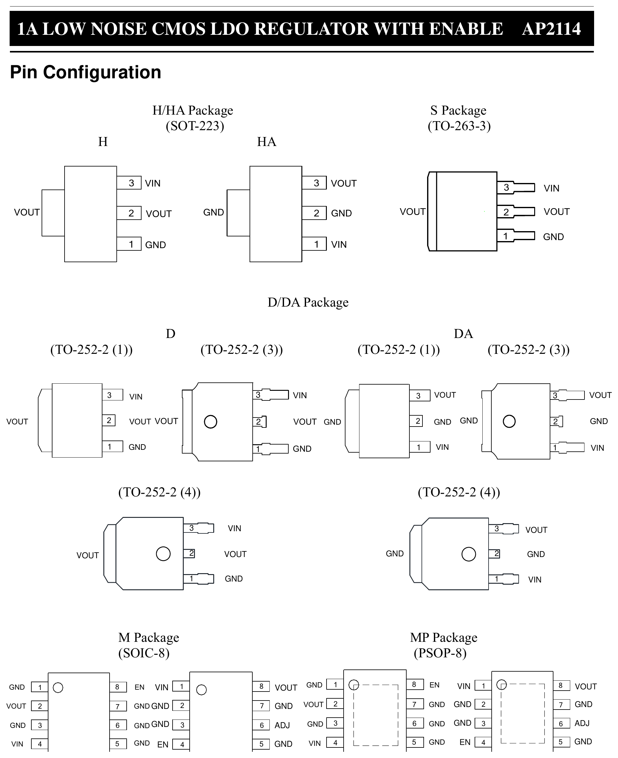
Pin Configuration
Multiple packages available. Top-view mapping:
| Package | Pin 1 | Pin 2 | Pin 3 | Pin 4 (if 4+) | Notes |
|---|---|---|---|---|---|
| H/HA (SOT-223) | GND | V<sub>OUT</sub> (2), V<sub>OUT</sub> tab | V<sub>IN</sub> | — | HA variant swaps order |
| S (TO-263-3) | GND | V<sub>OUT</sub> | V<sub>IN</sub> | — | Tab = V<sub>OUT</sub> |
| D/DA (TO-252-2) | GND | V<sub>OUT</sub> | V<sub>IN</sub> | — | Multiple pin-orientation variants (1)/(3)/(4) |
| M (SOIC-8, Fixed) | GND | V<sub>OUT</sub> | GND | V<sub>IN</sub> | EN on pin 8; pins 5-7 are additional GND |
| M (SOIC-8, Adjustable) | V<sub>OUT</sub> | GND | ADJ | V<sub>IN</sub> | EN on pin 8; pin 6 = ADJ |
| MP (PSOP-8, Fixed) | GND | V<sub>OUT</sub> | GND | V<sub>IN</sub> | Same as SOIC-8 layout |
| MP (PSOP-8, Adjustable) | V<sub>OUT</sub> | GND | ADJ | V<sub>IN</sub> | Same as SOIC-8 adjustable layout |
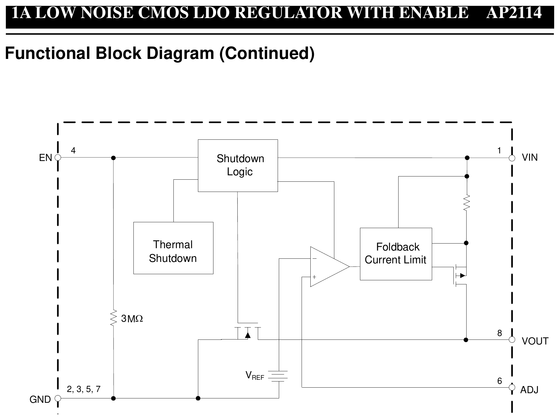
EN (pin 8 on SOIC/PSOP): Chip Enable. H = normal work, L = shutdown output.
Source: BCD Semiconductor / Diodes Incorporated AP2114 Datasheet Manufacturer: Diodes Incorporated (BCD Semiconductor) Part Number: AP2114 Document: Rev 2.2, January 2013 (1 A Low Noise CMOS LDO Regulator with Enable)
Absolute Maximum Ratings
| Parameter | Symbol | Value | Unit |
|---|---|---|---|
| Power Supply Voltage | V<sub>IN</sub> | 6.5 | V |
| Operating Junction Temperature | T<sub>J</sub> | 150 | °C |
| Storage Temperature Range | T<sub>STG</sub> | −65 to 150 | °C |
| Lead Temperature (Soldering, 10 s) | T<sub>LEAD</sub> | 260 | °C |
| θ<sub>JA</sub> (SOIC-8) | — | 144 | °C/W |
| θ<sub>JA</sub> (PSOP-8) | — | 43.7 | °C/W |
| θ<sub>JA</sub> (SOT-223) | — | 55.9 | °C/W |
| θ<sub>JA</sub> (TO-252-2 (1)(3)(4)) | — | 35 | °C/W |
| θ<sub>JA</sub> (TO-263-3) | — | 22 | °C/W |
| ESD (Machine Model) | — | 400 | V |
| ESD (Human Body Model) | — | 4000 | V |
Recommended Operating Conditions
| Parameter | Symbol | Min | Max | Unit |
|---|---|---|---|---|
| Supply Voltage | V<sub>IN</sub> | 2.5 | 6.0 | V |
| Operating Ambient Temperature Range | T<sub>A</sub> | −40 | +85 | °C |
Electrical Characteristics
AP2114-1.2 electrical characteristics: V<sub>IN</sub> = 2.5 V, C<sub>IN</sub> = 4.7 µF (ceramic), C<sub>OUT</sub> = 4.7 µF (ceramic), T<sub>A</sub> = 25 °C typical. Bold applies over −40 to +85 °C unless otherwise specified.
| Parameter | Symbol | Conditions | Min | Typ | Max | Unit |
|---|---|---|---|---|---|---|
| Output Voltage | V<sub>OUT</sub> | V<sub>IN</sub> = 2.5 V, 1 mA ≤ I<sub>OUT</sub> ≤ 30 mA | V<sub>OUT</sub>·98.5 % | 1.2 | V<sub>OUT</sub>·101.5 % | V |
| Input Voltage | V<sub>IN</sub> | 6.0 | V | |||
| Maximum Output Current | I<sub>OUT(MAX)</sub> | V<sub>IN</sub> = 2.5 V, V<sub>OUT</sub> ≥ 1.182 V to 1.218 V | 1 | A | ||
| Load Regulation | ΔV<sub>OUT</sub>/V<sub>OUT</sub>/ΔI<sub>OUT</sub> | V<sub>IN</sub> = 2.5 V, 1 mA ≤ I<sub>OUT</sub> ≤ 1 A | 0.2 | 1 | %/A | |
| Line Regulation | ΔV<sub>OUT</sub>/V<sub>OUT</sub>/V<sub>IN</sub> | 2.5 V ≤ V<sub>IN</sub> ≤ 6 V, I<sub>OUT</sub> = 30 mA | −0.1 | 0.02 | 0.1 | %/V |
| Dropout Voltage | V<sub>DROP</sub> | I<sub>OUT</sub> = 1 A | 1200 | 1300 | mV | |
| Quiescent Current | I<sub>Q</sub> | V<sub>IN</sub> = 2.5 V, I<sub>OUT</sub> = 0 mA | 60 | 75 | µA | |
| PSRR | — | Ripple 1 V<sub>p-p</sub>, V<sub>IN</sub> = 2.5 V, I<sub>OUT</sub> = 100 mA, f = 100 Hz | 68 | dB | ||
| PSRR | — | f = 1 kHz | 68 | dB | ||
| Output Voltage Temperature Coefficient | ΔV<sub>OUT</sub>/V<sub>OUT</sub>/ΔT | I<sub>OUT</sub> = 30 mA, T<sub>A</sub> = −40 °C to 85 °C | ±30 | ppm/°C | ||
| Short Current Limit | I<sub>SHORT</sub> | V<sub>OUT</sub> = 0 V | 50 | mA | ||
| Standby Current | I<sub>STD</sub> | V<sub>IN</sub> = 2.5 V, V<sub>EN</sub> in OFF mode | 0.01 | 1.0 | µA | |
| RMS Output Noise | V<sub>NOISE</sub> | 10 Hz ≤ f ≤ 100 kHz (No Load) | 30 | µV<sub>RMS</sub> | ||
| V<sub>EN</sub> High Voltage | V<sub>IH</sub> | Enable logic high, regulator on | 1.5 | V | ||
| V<sub>EN</sub> Low Voltage | V<sub>IL</sub> | Enable logic low, regulator off | 0.4 | V | ||
| Start-up Time | t<sub>S</sub> | No load | 20 | µs | ||
| EN Pull-Down Resistor | R<sub>PD</sub> | 3.0 | MΩ | |||
| V<sub>OUT</sub> Discharge Resistor | R<sub>DCHG</sub> | Set EN pin at Low | 60 | Ω | ||
| Thermal Shutdown Temperature | T<sub>OTSD</sub> | 160 | °C | |||
| Thermal Shutdown Hysteresis | T<sub>HYSTSD</sub> | 25 | °C |
Packages
Available as:
- SOT-223 (H/HA)
- TO-263-3 (S)
- TO-252-2 (D, DA, various pin orientations (1), (3), (4))
- SOIC-8 (M)
- PSOP-8 (MP)
Output voltages: 1.2 V, 1.5 V, 1.8 V, 2.5 V, 3.3 V, and adjustable (0.8 V – 5.0 V).
Applications
- LCD monitor
- LCD TV
- Set-top box (STB)
Applications
- LCD monitor
- LCD TV
- Set-top box (STB)
Usage notes
- Input and output require ceramic, tantalum, or aluminum electrolytic capacitors; 4.7 µF is a flexible default.
- The EN pin has a 3 MΩ internal pull-down, so it defaults OFF if left floating.
- At shutdown (EN low), V<sub>OUT</sub> is actively pulled down through a 60 Ω discharge resistor.
- To prevent short-circuit protection from being prematurely activated, the input voltage must be applied before a current-source load is applied.
Diagrams & Graphs (3)
**Source:** [BCD Semiconductor / Diodes Incorporated AP2114 Datasheet](https://www.diodes.com/assets/Datasheets/AP2114.pdf)
**Manufacturer:** Diodes Incorporated (BCD Semiconductor)
**Part Number:** AP2114
**Document:** Rev 2.2, January 2013 (1 A Low Noise CMOS LDO Regulator with Enable)

## Description

The AP2114 is a CMOS process low-dropout linear regulator with enable function. The regulator delivers a guaranteed 1 A (min) continuous load current. The AP2114 is available in 1.2 V, 1.5 V, 1.8 V, 2.5 V and 3.3 V regulator output and 0.8 V to 5 V adjustable output. It features excellent output accuracy of ±1.5 %, and it is also available in an excellent load regulation and line regulation performance.

The AP2114 features low power consumption.

Packages: SOT-223, TO-252-2(1) / (3) / (4), TO-263-3, SOIC-8, PSOP-8.

## Key Specifications

| Parameter | Value |
| --- | --- |
| Output Voltage Accuracy | ±1.5 % |
| Output Current | 1 A (min) |
| Foldback Short Circuit Protection | 50 mA |
| Low Dropout Voltage (3.3 V) | 450 mV typ @ I<sub>OUT</sub> = 1 A |
| Excellent Line Regulation | 0.02 %/V typ, 0.1 %/V max @ I<sub>OUT</sub> = 30 mA |
| Excellent Load Regulation | 0.25 %/A typ @ I<sub>OUT</sub> = 1 mA to 1 A |
| Low Quiescent Current | 60 µA (1.2 V/1.5 V/1.8 V/2.5 V/ADJ) typ |
| Low Output Noise | 30 µV<sub>RMS</sub> |
| PSRR | 68 dB @ 1 kHz (I<sub>OUT</sub> = 100 mA) |
| OTSD Protection | Yes |
| Operating Temperature Range | −40 °C to +85 °C |
| ESD | MM 400 V, HBM 4000 V |
| Stability | 4.7 µF flexible cap: ceramic, tantalum, aluminum electrolytic |

## Features

- Output voltage accuracy ±1.5 %
- Output current 1 A (min)
- Foldback short-circuit protection 50 mA
- Low dropout voltage 450 mV (typ) @ I<sub>OUT</sub> = 1 A for 3.3 V version
- Stable with 4.7 µF flexible cap: ceramic, tantalum, aluminum electrolytic
- Excellent line regulation 0.02 % (typ), 0.1 % (max) @ I<sub>OUT</sub> = 30 mA
- Excellent load regulation 0.25 % (typ) @ I<sub>OUT</sub> = 1 mA to 1 A
- Low quiescent current 60 µA (1.2 V/1.5 V/1.8 V/2.5 V/ADJ)
- Low output noise 30 µV<sub>RMS</sub>
- PSRR 68 dB @ freq = 1 kHz (1.2 V/1.5 V/1.8 V/ADJ)
- OTSD protection
- Operating temperature range −40 °C to +85 °C
- ESD: MM 400 V, HBM 4000 V

## Applications

- LCD monitor
- LCD TV
- Set-top box (STB)

## Pin Configuration

Multiple packages available. Top-view mapping:

| Package | Pin 1 | Pin 2 | Pin 3 | Pin 4 (if 4+) | Notes |
| --- | --- | --- | --- | --- | --- |
| H/HA (SOT-223) | GND | V<sub>OUT</sub> (2), V<sub>OUT</sub> tab | V<sub>IN</sub> | — | HA variant swaps order |
| S (TO-263-3) | GND | V<sub>OUT</sub> | V<sub>IN</sub> | — | Tab = V<sub>OUT</sub> |
| D/DA (TO-252-2) | GND | V<sub>OUT</sub> | V<sub>IN</sub> | — | Multiple pin-orientation variants (1)/(3)/(4) |
| M (SOIC-8, Fixed) | GND | V<sub>OUT</sub> | GND | V<sub>IN</sub> | EN on pin 8; pins 5-7 are additional GND |
| M (SOIC-8, Adjustable) | V<sub>OUT</sub> | GND | ADJ | V<sub>IN</sub> | EN on pin 8; pin 6 = ADJ |
| MP (PSOP-8, Fixed) | GND | V<sub>OUT</sub> | GND | V<sub>IN</sub> | Same as SOIC-8 layout |
| MP (PSOP-8, Adjustable) | V<sub>OUT</sub> | GND | ADJ | V<sub>IN</sub> | Same as SOIC-8 adjustable layout |

EN (pin 8 on SOIC/PSOP): Chip Enable. H = normal work, L = shutdown output.

## Absolute Maximum Ratings

| Parameter | Symbol | Value | Unit |
| --- | --- | --- | --- |
| Power Supply Voltage | V<sub>IN</sub> | 6.5 | V |
| Operating Junction Temperature | T<sub>J</sub> | 150 | °C |
| Storage Temperature Range | T<sub>STG</sub> | −65 to 150 | °C |
| Lead Temperature (Soldering, 10 s) | T<sub>LEAD</sub> | 260 | °C |
| θ<sub>JA</sub> (SOIC-8) | — | 144 | °C/W |
| θ<sub>JA</sub> (PSOP-8) | — | 43.7 | °C/W |
| θ<sub>JA</sub> (SOT-223) | — | 55.9 | °C/W |
| θ<sub>JA</sub> (TO-252-2 (1)(3)(4)) | — | 35 | °C/W |
| θ<sub>JA</sub> (TO-263-3) | — | 22 | °C/W |
| ESD (Machine Model) | — | 400 | V |
| ESD (Human Body Model) | — | 4000 | V |

## Recommended Operating Conditions

| Parameter | Symbol | Min | Max | Unit |
| --- | --- | --- | --- | --- |
| Supply Voltage | V<sub>IN</sub> | 2.5 | 6.0 | V |
| Operating Ambient Temperature Range | T<sub>A</sub> | −40 | +85 | °C |

## Electrical Characteristics

AP2114-1.2 electrical characteristics: V<sub>IN</sub> = 2.5 V, C<sub>IN</sub> = 4.7 µF (ceramic), C<sub>OUT</sub> = 4.7 µF (ceramic), T<sub>A</sub> = 25 °C typical. **Bold** applies over −40 to +85 °C unless otherwise specified.

| Parameter | Symbol | Conditions | Min | Typ | Max | Unit |
| --- | --- | --- | --- | --- | --- | --- |
| Output Voltage | V<sub>OUT</sub> | V<sub>IN</sub> = 2.5 V, 1 mA ≤ I<sub>OUT</sub> ≤ 30 mA | V<sub>OUT</sub>·98.5 % | 1.2 | V<sub>OUT</sub>·101.5 % | V |
| Input Voltage | V<sub>IN</sub> | | | | 6.0 | V |
| Maximum Output Current | I<sub>OUT(MAX)</sub> | V<sub>IN</sub> = 2.5 V, V<sub>OUT</sub> ≥ 1.182 V to 1.218 V | 1 | | | A |
| Load Regulation | ΔV<sub>OUT</sub>/V<sub>OUT</sub>/ΔI<sub>OUT</sub> | V<sub>IN</sub> = 2.5 V, 1 mA ≤ I<sub>OUT</sub> ≤ 1 A | | 0.2 | 1 | %/A |
| Line Regulation | ΔV<sub>OUT</sub>/V<sub>OUT</sub>/V<sub>IN</sub> | 2.5 V ≤ V<sub>IN</sub> ≤ 6 V, I<sub>OUT</sub> = 30 mA | −0.1 | 0.02 | 0.1 | %/V |
| Dropout Voltage | V<sub>DROP</sub> | I<sub>OUT</sub> = 1 A | | 1200 | 1300 | mV |
| Quiescent Current | I<sub>Q</sub> | V<sub>IN</sub> = 2.5 V, I<sub>OUT</sub> = 0 mA | | 60 | 75 | µA |
| PSRR | — | Ripple 1 V<sub>p-p</sub>, V<sub>IN</sub> = 2.5 V, I<sub>OUT</sub> = 100 mA, f = 100 Hz | | 68 | | dB |
| PSRR | — | f = 1 kHz | | 68 | | dB |
| Output Voltage Temperature Coefficient | ΔV<sub>OUT</sub>/V<sub>OUT</sub>/ΔT | I<sub>OUT</sub> = 30 mA, T<sub>A</sub> = −40 °C to 85 °C | | ±30 | | ppm/°C |
| Short Current Limit | I<sub>SHORT</sub> | V<sub>OUT</sub> = 0 V | | 50 | | mA |
| Standby Current | I<sub>STD</sub> | V<sub>IN</sub> = 2.5 V, V<sub>EN</sub> in OFF mode | | 0.01 | 1.0 | µA |
| RMS Output Noise | V<sub>NOISE</sub> | 10 Hz ≤ f ≤ 100 kHz (No Load) | | 30 | | µV<sub>RMS</sub> |
| V<sub>EN</sub> High Voltage | V<sub>IH</sub> | Enable logic high, regulator on | 1.5 | | | V |
| V<sub>EN</sub> Low Voltage | V<sub>IL</sub> | Enable logic low, regulator off | | | 0.4 | V |
| Start-up Time | t<sub>S</sub> | No load | | 20 | | µs |
| EN Pull-Down Resistor | R<sub>PD</sub> | | | 3.0 | | MΩ |
| V<sub>OUT</sub> Discharge Resistor | R<sub>DCHG</sub> | Set EN pin at Low | | 60 | | Ω |
| Thermal Shutdown Temperature | T<sub>OTSD</sub> | | | 160 | | °C |
| Thermal Shutdown Hysteresis | T<sub>HYSTSD</sub> | | | 25 | | °C |

## Packages

Available as:
- SOT-223 (H/HA)
- TO-263-3 (S)
- TO-252-2 (D, DA, various pin orientations (1), (3), (4))
- SOIC-8 (M)
- PSOP-8 (MP)

Output voltages: 1.2 V, 1.5 V, 1.8 V, 2.5 V, 3.3 V, and adjustable (0.8 V – 5.0 V).

## Applications

- LCD monitor
- LCD TV
- Set-top box (STB)

### Usage notes

- Input and output require ceramic, tantalum, or aluminum electrolytic capacitors; 4.7 µF is a flexible default.
- The EN pin has a 3 MΩ internal pull-down, so it defaults OFF if left floating.
- At shutdown (EN low), V<sub>OUT</sub> is actively pulled down through a 60 Ω discharge resistor.
- To prevent short-circuit protection from being prematurely activated, the input voltage must be applied before a current-source load is applied.
Sub-Skills
What are Sub-Skills?
Sub-skills are community-contributed AI skill extensions for this component.
They teach AI assistants about specific tools, configurators, or workflows.
Examples:
- A manufacturer’s configuration tool for a motor controller
- A community-written design guide for an amplifier circuit
- An automated test/validation script for a sensor module
How to add one: Click Add Sub-Skill, provide the URL
to your skill and a brief description. Submissions are reviewed by the Adom team
before going live.
Sub-skills are community-contributed AI skill extensions for this component. They teach AI assistants about specific tools, configurators, or workflows.
Examples:
- A manufacturer’s configuration tool for a motor controller
- A community-written design guide for an amplifier circuit
- An automated test/validation script for a sensor module
How to add one: Click Add Sub-Skill, provide the URL to your skill and a brief description. Submissions are reviewed by the Adom team before going live.
No sub-skills yet. Be the first to contribute one!